IPE300 series engineering VFD Communication protocol
-273-
Max. transmission
distance
Max. transmission
distance
In long-distance RS485 communication, it is recommended that you use shielded cables, and use the
shielding layer as the ground wire.
When there are fewer devices and the transmission distance is short, the whole network works well
without terminal load resistors. The performance, however, degrades as the distance increases.
Therefore, it is recommended that you use a 120 Ω terminal resistor when the transmission distance
is long.
9.3.1.1 Application to one VFD
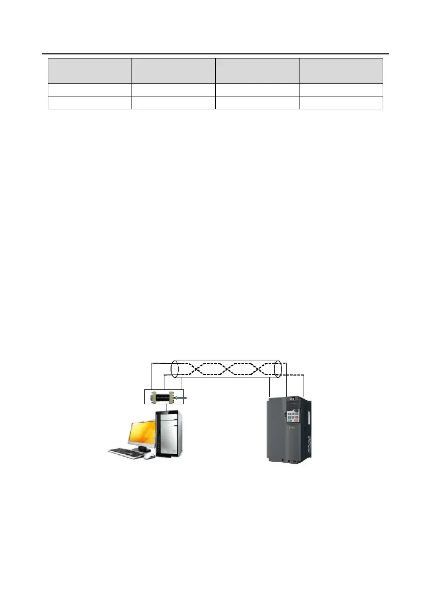
Figure 9-1 is the Modbus wiring diagram for the network with one VFD and PC. Generally, PCs do not
provide RS485 interfaces, so you need to convert an RS232 or USB interface of a PC to an RS485
interface through an adapter. Connect end A of the RS485 interface to the 485+ port on the terminal
block of the VFD, and connect end B to the 485- port. It is recommended that you use shielded
twisted pairs. When an RS232-RS485 adapter is used, the cable used to connect the RS232 interface
of the PC and the adapter cannot be longer than 15m. Use a short cable when possible. It is
recommended that you insert the adapter directly into the PC. Similarly, when a USB-RS485 adapter
is used, use a short cable when possible.
When the wiring is completed, select the correct port (for example, COM1 to connect to the
RS232-RS485 adapter) for the upper computer of the PC, and keep the settings of basic parameters
such as communication baud rate and data check bit consistent with those of the VFD.
PC
VFD
GroundA B
B
A
RS485 line
RS232-RS485 converter
Shielded twisted pair
Ground
485- 485+
Figure 9-1 Wiring of RS485 applied to one VFD
9.3.1.2 Application to multiple VFDs
In pratical application to multiple VFDs, chrysanthemum connection and star connection are
commonly used.
According to the requirements of the RS485 industrial bus standards, all the devices need to be

 Loading...


