IPE300 series engineering VFD Communication protocol
-274-
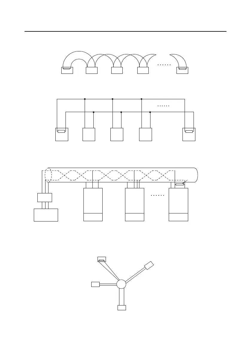
connected in chrysanthemum mode with one 120 Ω terminal resistor on each end, as shown in Figure
9-2. Figure 9-3 is the simplified wiring diagram, and Figure 9-4 is the practical application diagram.
1# 2
#
3 # 4 # 32 #
120Ω
120Ω
Figure 9-2 On-site chrysanthemum connection diagram
1# 2# 3# 31#Master
A+
B-
A+ B-
Figure 9-3 Simplified chrysanthemum connection diagram
INVT
VFD
Address 1
Earth
485+
485-
485+
485-
485+
485-
120Ω
Terminal resistor
PC
Converter
GND
RS232-RS485
Max. length of the
cable: 15 m
Shielded twisted pair
Address 2 Address N
INVT
VFD
INVT
VFD
Earth Earth
Figure 9-4 Practical application diagram of chrysanthemum connection
Figure 9-5 shows the start connection diagram. When this connection mode is adopted, each of the
two devices that are farthest away from each other on the line must be configured with a terminal
resistor (in this figure, the two devices are devices 1# and 15#).
1#
15#
32#
6
#
Main control
device
Figure 9-5 Star connection

 Loading...


