IPE300 series engineering VFD Extension card
-315-
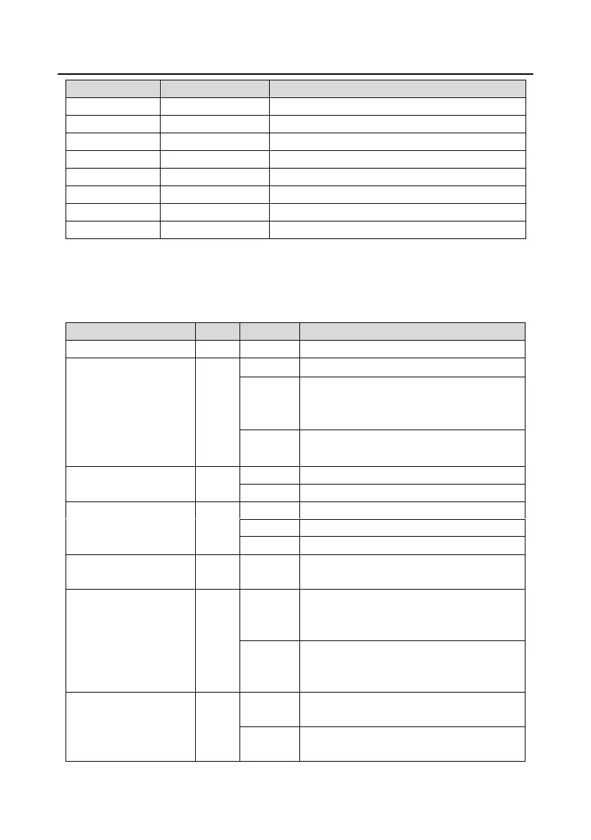
Indicator definition:
The PROFINET communication card has 9 indicators, among which LED1 is the power indicator,
LED2–5 are the communication status indicators of the communication card, and LED6–9 are the
status indicators of the network port.
LED2 (Bus status
indicator)
The connection to the network cable between
the PROFINET controller is normal, but the
communication is not established.
Communication with the PROFINET controller
has been established.
LED3 (System fault
indicator)
PROFINET diagnosis exists.
LED4 (Slave ready
indicator)
TPS-1 protocol stack has started.
TPS-1 waits for MCU initialization.
TPS-1 protocol stack does not start.
LED5 (Maintenance status
indicator)
Manufacturer-specific, depending on the
characteristics of the device
LED6/7 (Network port
status indicator)
The PROFINET communication card and
PC/PLC have been connected by using a
network cable.
The connection between the PROFINET
communication card and PC/PLC has not been
established.
LED8/9 (Network port
communication indicator)
The PROFINET communication card and
PC/PLC are communicating.
The PROFINET communication card and
PC/PLC have no communication yet.
 Loading...


