IPE300 series engineering VFD Extension card
-325-
1. Applicable to 5V/12V push-pull encoders
2. Applicable to 5V/12V OC encoders
3. Applicable to 5V differential encoders
4. Response frequency: 200 kHz
1. Supporting the same signal types as the encoder signal
types
2. Response frequency: 200 kHz
1. Differential output of 5V
2. Supporting frequency division of 1–255, which can be
set through P20.16 or P24.16
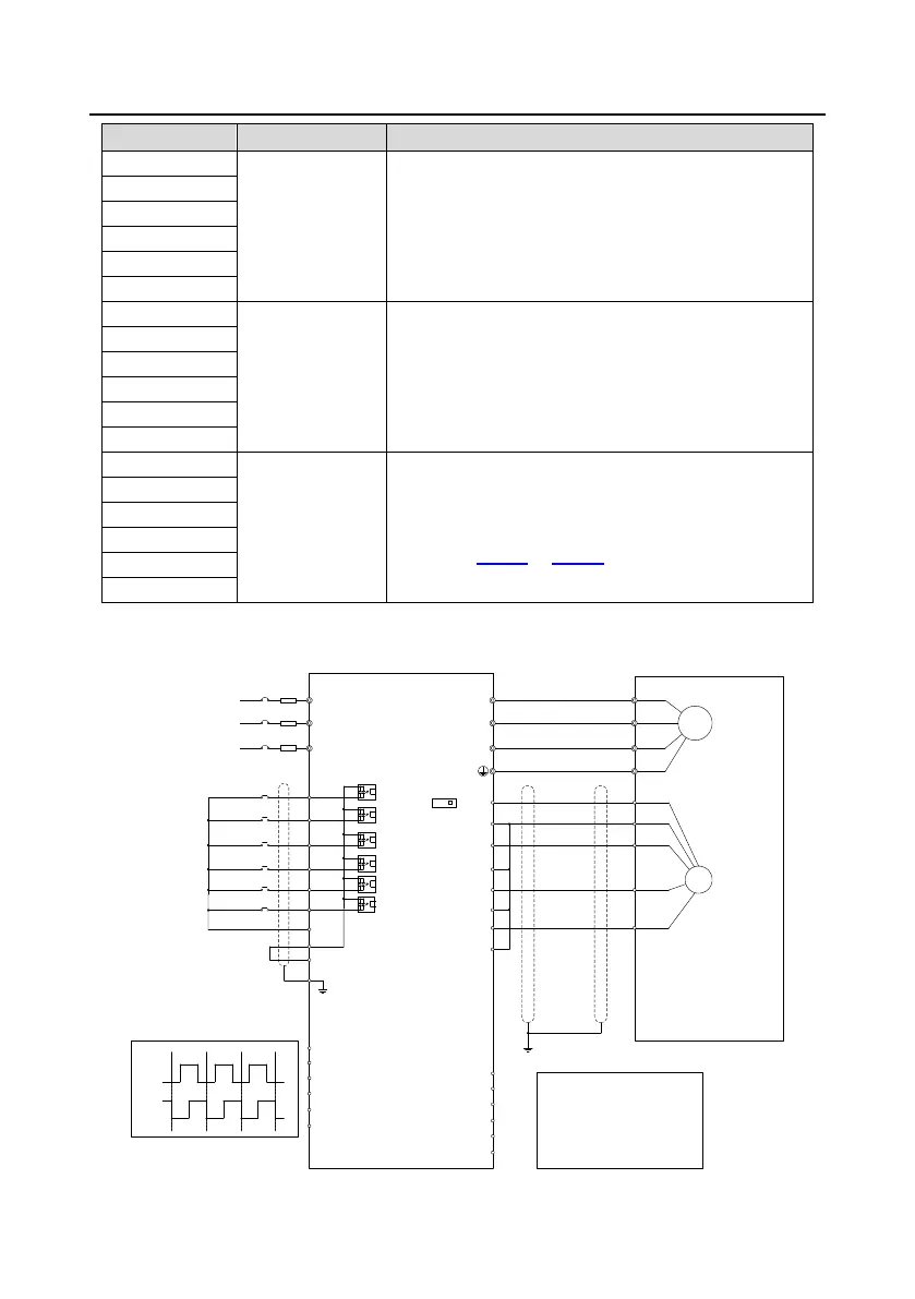
The following figure shows the external wiring when the extension card is used in combination with an
open collector encoder. A pull-up resistor is configured inside the PG card.
+24V
PE
COM
S4
S3
S2
S1
HDIB
PW
HDIA
A1-
B1+
B1-
Z1+
Z1-
R
S
T
U
V
W
U
V
W
M3~
PG
AO+
AO-
BO+
BO-
ZO+
ZO-
pulse A
pulse B
A2+
A2-
B2+
B2-
FWD jog
FWD run
CNC
PLC
Upper computer
A1+
Fault reset
Z2+
Z2-
PGND
PWR
5V
12V
SW1
Z
B
A
 Loading...


