IPE300 series engineering VFD Optional peripheral accessories
-365-
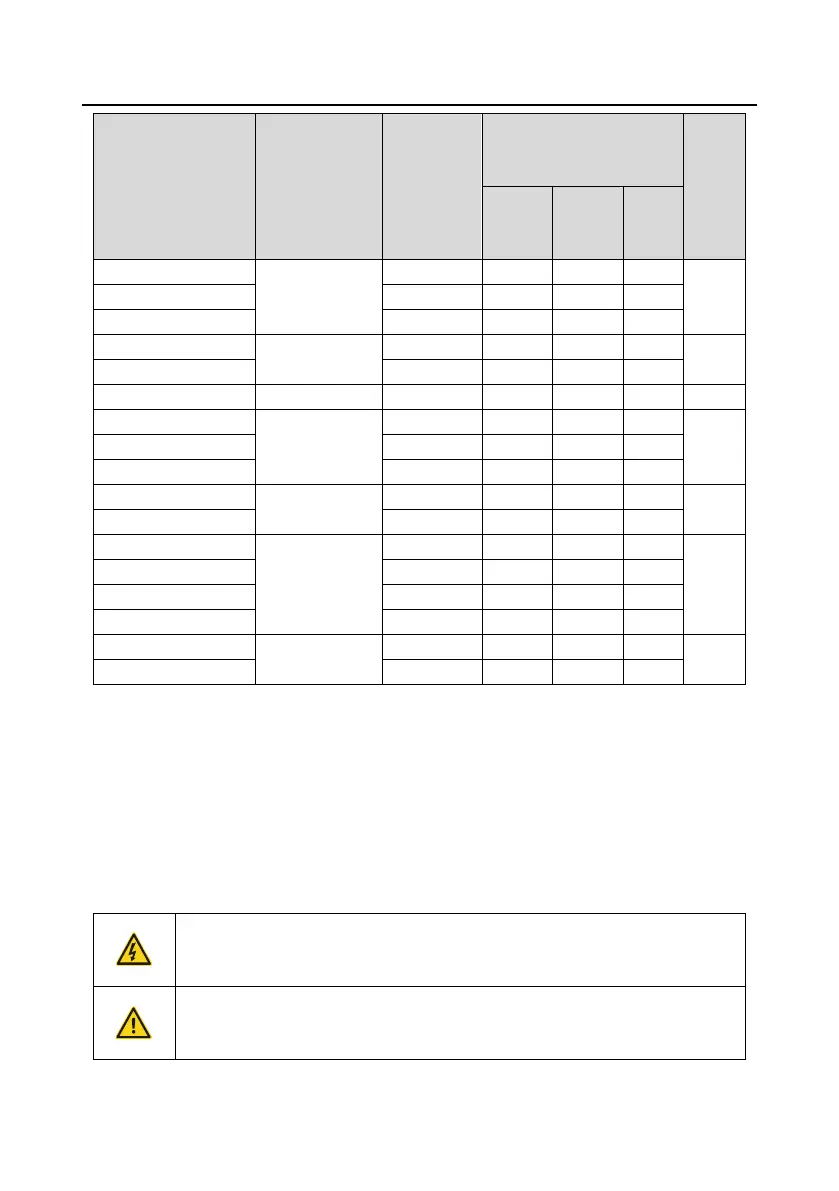
Resistance
applicable
for 100%
braking
torque
(Ω)
Braking resistor
dissipation power
(kW)
Min.
allowed
braking
resista
nce
(Ω)
Quantity: Two
DBU100H-320-4
Quantity: Two
DBU100H-400-4
Note:
Select braking resistors according to the resistance and power data provided by INVT.
The braking resistor may increase the braking torque of the VFD. The preceding table describes
the resistance and power for 100% braking torque, 10% braking usage, 50% braking usage, and
80% braking usage. You can select the braking system based on the actual operation conditions.
When using an external braking unit, set the brake voltage class of the braking unit properly by
referring to the manual of the dynamic braking unit. If the voltage class is set incorrectly, the VFD
may not run properly.
Do not use braking resistors whose resistance is lower than the specified
minimum resistance. The VFD does not provide protection against overcurrent
caused by resistors with low resistance.
In scenarios where braking is frequently implemented, that is, the braking usage
is greater than 10%, you need to select a braking resistor with higher power as
required by the operation conditions according to the preceding table.
 Loading...


