IPE300 series engineering VFD Installation guidance
-29-
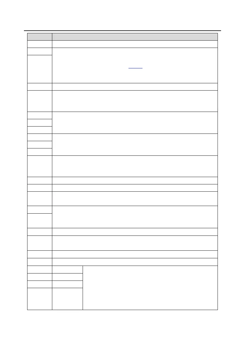
Locally provided +10.5V power supply
Input range: For AI1, 0–10V or 0–20mA; For AI2, -10V – +10V
Input impedance: 20kΩ for voltage input or 250Ω for current input
AI1 voltage or current input is set by P05.50
Resolution: 5mV when 10V corresponds to 50Hz
Deviation: ±0.5% at 25°C, when input is above 5V/10mA
Reference zero potential of +10.5V
Output range: 0–10V or 0–20mA
Voltage or current output is set by toggle switch SW2
Deviation: ±0.5% at 25°C, when output is above 5V/10mA
RO1 output; RO1A: NO; RO1B: NC; RO1C: common
Contact capacity: 3A/AC250V, 1A/DC30V
RO2 output; RO2A: NO; RO2B: NC; RO2C: common
Contact capacity: 3A/AC250V, 1A/DC30V
Switch capacity: 200mA/30V
Output frequency range: 0–50kHz
Duty ratio: 50%
Common terminal of open collector output; short connected to COM by default
Switch capacity: 200mA/30V
Output frequency range: 0–1kHz
RS485 communication port, RS485 differential signal port and standard RS485
communication port must use twisted shielded pairs; the 120ohm terminal matching
resistor for RS485 communication is connected through the DIP switch SW3.
Used to provide input digital working power from the external to the internal
Voltage range: 12–24V
User power supply provided by the VFD. Max. output current: 200mA
Internal impedance: 3.3kΩ
12–30V voltage input is acceptable
Bi-direction input terminal, supporting both NPN and PNP
Max. input frequency: 1kHz
All are programmable digital input terminals, the functions of which
can be set through function codes

 Loading...


