TM3215, 3245, 3265
26
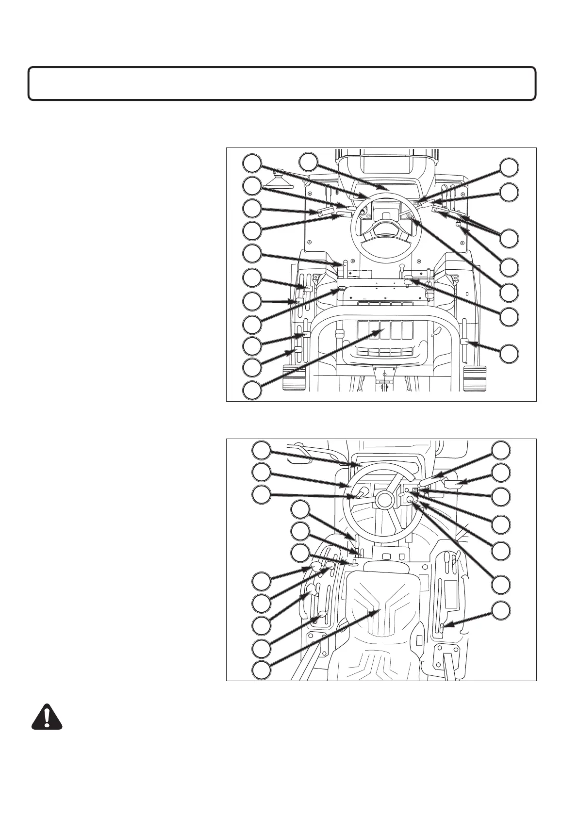
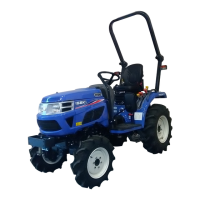
Generally layout and location of controls within operator’s area on tractor. Specific use of these controls is given later
in this section and also in “Operation” section of this operator’s manual:
FIG. 34: Mechanical Transmission
1. Instrument Panel
2. Steering Wheel
3. Clutch Pedal
4. Parking Brake
5. Mid PTO Lever (M Type)
6. 4-Wheel Drive Shift Lever
7. Seat
8. Differential Lock Pedal
9. Main Gear Shift Lever
10. Range Gear Shift Lever
11. Rear PTO Lever
12. 3-Point Hitch Control
13. Accelerator Pedal
14. Throttle Lever
15. Brake Pedals
16. Combination Switch (horn button,
headlamp switch, position lamp
switch, turn signal switch)
17. Forward / Reverse Shuttle Lever
18. Main Switch
19. Hazard Signal Switch
FIG. 35: Hydrostatic Transmission
1. Instrument Panel
2. Steering Wheel
3. PTO Switch
4. Parking Brake
5. Mid PTO Lever
6. 4-Wheel Drive Shift Lever
7. Seat
8. Differential Lock Pedal
9. Range Gear Shift Lever
10. Rear PTO Lever
11. 3-Point Hitch Control
12. Throttle Lever
13. Brake Pedal
14. Combination Switch (horn button,
headlamp switch, position lamp
switch, turn signal switch)
15. PTO Switch
16. Main Switch
17. Hazard Signal Switch
18. Cruise Control Lever
1
19
14
13
18
8
16
2
3
4
17
11
9
10
5
7
6
15
12
1 12
13
3
16
2
14
5
7
9
10
18
4
8
6
11
17
15
INSTRUMENTS & CONTROLS
FIG. 34 (Mechanical Transmission)
FIG. 35 (Hydrostatic Transmission)
CAUTION: Become familiar with all operat-
ing controls prior to operating tractor. Read
this operator’s manual in its entirety before
starting.



 To Next Page