TM3215, 3245, 3265
40
Normal Starting
CAUTION: Do not attempt to start the trac-
tor unless seated in the operator’s seat. Do
not allow anyone on the tractor except for
the operator.
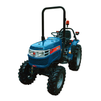
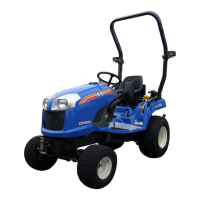
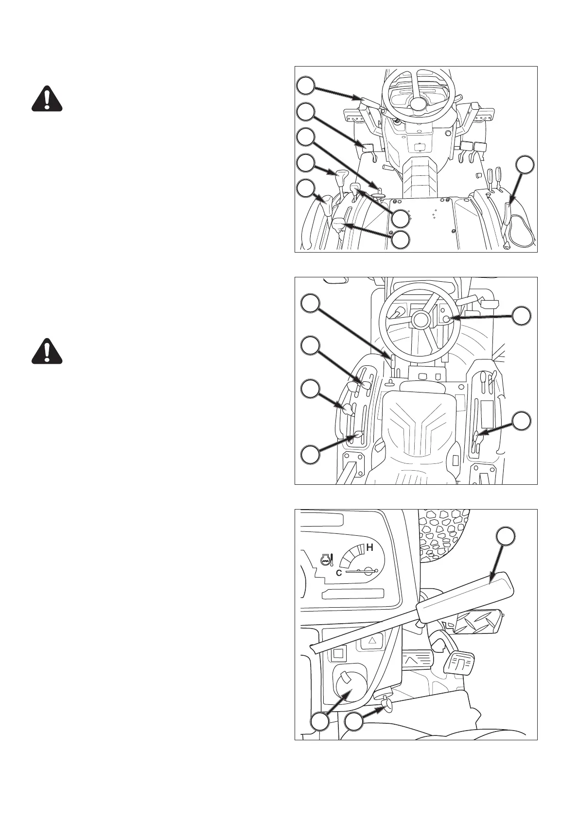
FIGS. 65, 66 & 67: To start the engine, proceed as fol-
lows:
1. Apply parking brake, 1.
2. (a) Mechanical Transmission
Place the main gear shift lever, 2, the range
gear shift lever, 3, and forward / reverse shuttle
lever, 11 in the neural position.
(b) Hydrostatic Transmission
Place the range gear shift lever, 3, in the
neutral position.
3. Make sure the rear PTO, 4, and mid PTO selector
levers, 5, are in the neutral position.
4. Fully depress the main clutch pedal, 6, to disengage
the clutch. (Mechanical Transmission)
5. Make sure the PTO switch, 7, is in the OFF position.
(Hydrostatic Transmission)
CAUTION: The operator being seated in the
operator’s seat, the gear shift lever must be
in neutral and the PTO levers must be in
neutral to actuate safety switches and per-
mit operation of the starter motor.
6. Set the position control lever, 8, (3-point hitch) in the
down position.
7. Turn the main switch, 9, to the “glow” position for
5-10 seconds.
8. Set the throttle lever, 10, at half to the fully open
position.
9. Turn the main switch, 9, to the “on” position for 1-2
seconds, then turn to the “start” position. Release
the switch the moment engine starts.
10. Once the engine runs smoothly, set engine speed to
approximately 1,500 min-1 to allow the engine and
hydraulic system to warm up for several minutes.
DO NOT LOAD A COLD ENGINE.
IMPORTANT: Do not crank the engine for more than
10 seconds at a time. Allow the starter
to cool at least 20 seconds before re-
peating procedure. Never turn the main
switch to “start” with the engine running.
Severe damage will result.
The battery charge indicator lamp and engine oil pres-
sure lamp on the indicator light strip should go out when
the engine starts. If either light remains lit, STOP THE
ENGINE IMMEDIATELY and investigate source of prob-
lem.
NOTE: If the engine will not start and run after several
attempts, refer to “Maintenance” section in this
operator’s manual and bleed any air that may
be present in the fuel system.
1
2
3
11
8
4
5
6
7
1
4
3
5
8
10
7 9
FIG. 65 (Mechanical Transmission)
FIG. 66 (Hydrostatic Transmission)
FIG. 67
 Loading...