TM3215, 3245, 3265
58
Detaching Implements
CAUTION: Always use POSITION CONTROL
to attach / detach implements to provide
precise control of the hitch.
Select a level to detach and store the implement.
Lower implement to ground by moving the position
control lever to DOWN. If necessary, adjust the level-
ing crank on the right lift link to level the implement on
ground.
Shut off the engine, securely lock the brakes and re-
move the main switch key from the tractor.
Disconnect the implement PTO drive shaft (as appli-
cable). Detach the top link from the implement.
NOTE: Lengthening or shortening of the top link may
be required to permit disconnection from the
implement.
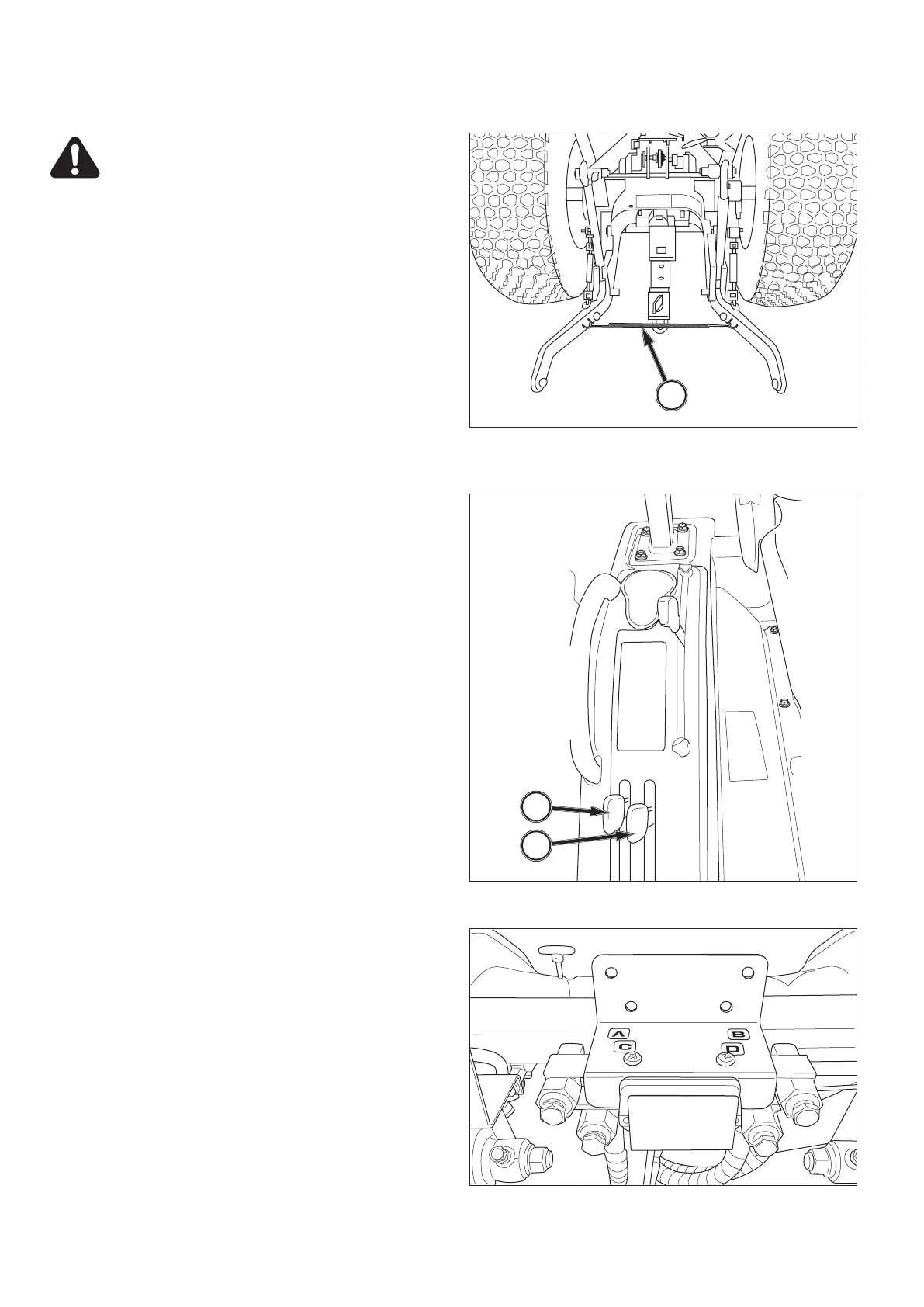
FIG. 100: Disconnect the lower links from the implement
pins. Make sure the lower links are connected together
with the spring, 1, to prevent tire interference.
Take position in the operator’s seat, start the engine and
drive the tractor clear of the implement.
External Auxiliary Hydraulics
Auxiliary hydraulics can be installed to operate imple-
ments requiring external hydraulic source for operation.
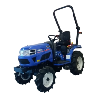
FIG. 101: Control lever, 1, controls implement raising /
lowering when first set of remote couplers are used.
Control lever, 2, controls implement when second set of
remote couplers are used.
Control lever(s) are spring-loaded to center neutral posi-
tion, from normal raise or lower positions.
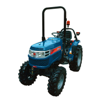
FIG. 102: Remote couplers are located at rear of tractor,
above 3-point hitch, or, under right step (depending on
kit installed). Rear location shown.
Coupler set, 1, corresponds with control lever, 1, coupler
set, 2, with control lever, 2.
Implement hoses must be connected to each coupler
set so when respective control lever is pulled backward,
implement raises and, when pushed forward, implement
lowers. Male coupler tips (on implement hoses) must
be compatible with tractor couplers and must also be
inserted fully and locked into tractor couplers to operate
correctly.
1
2
1
FIG. 100
FIG. 101
FIG. 102



 To Next Page