TM3215, 3245, 3265
80
When operating for the first time or after
long term storage, check if the battery
charge level is enough. (If measurement
of battery voltage is available, check if
the voltage is more than 12.5 V.) When
the tractor is stored more than 2 months
in summer or 3 months in winter, charge
the battery.
Starting Switches
This tractor is equipped with a neutral-start system con-
sisting of neutral switches and a relay. To start tractor,
ALL the following is required:
(Mechanical Transmission)
Depress clutch pedal.
Main gear shift lever and range gear shift lever must
be in neutral position.
PTO control lever must be in neutral (OFF) position.
Mid PTO control lever must be in neutral (OFF)
position.
(Hydrostatic Transmission)
Range gear shift lever must be in neutral position.
PTO control switch must be OFF position.
Wiring / Fuse Arrangement
CAUTION: Keep all wiring connections
clean and tight. Make sure wiring is correct-
ly secured to prevent damage.
CAUTION: DO NOT alter wiring by adding
“home-made” extensions or replacements.
Doing so can eliminate fuse protection and /
or eliminate safety features of the system.
CAUTION: The tractor is equipped with neg-
ative (-) ground system. Tractor metal parts
provide many electrical connections. For
this reason, all positive (+) circuits must be
insulated to prevent “grounding” or short
circuits and prevent possible fire.
CAUTION: DO NOT replace any fuse with a
fuse of higher amperage rating. DO NOT
use wire (or foil) to by-pass fuse protection.
Fire can result. If fuses blow repeatedly, ex-
amine the electrical system for “earthed” or
“shorted” circuits.
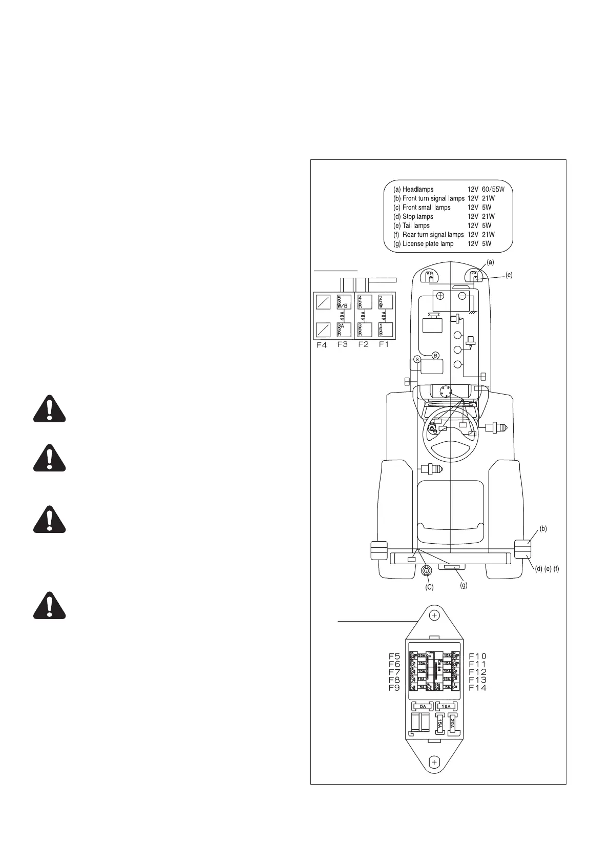
FIG. 146: General layout and location of electrical sys-
tem components and fuses:
• Main Fuse Box, A - Located inside right hand fan
cover.
Slow blow fuse box is in left fan cover.
IMPORTANT: Slow blow fuses are of specific Use only
authorized parts for replacements.
Main Fuse Box
Auxiliary Source BATT
Light Horn
Head light
Brake lamp
Key stop relay
Winker, Hazard
ACC, Meter panel
Auxiliary source ACC
PTO, Pump
Glow monitor
Slow blow
Alternator
Main source
Key stop solenoid
Vacant
FIG. 146



 To Next Page