INSTRUMENTS & CONTROLS
29
CAUTION: DO NOT service hot engine. Al-
low to completely cool before servicing or
removing radiator cap
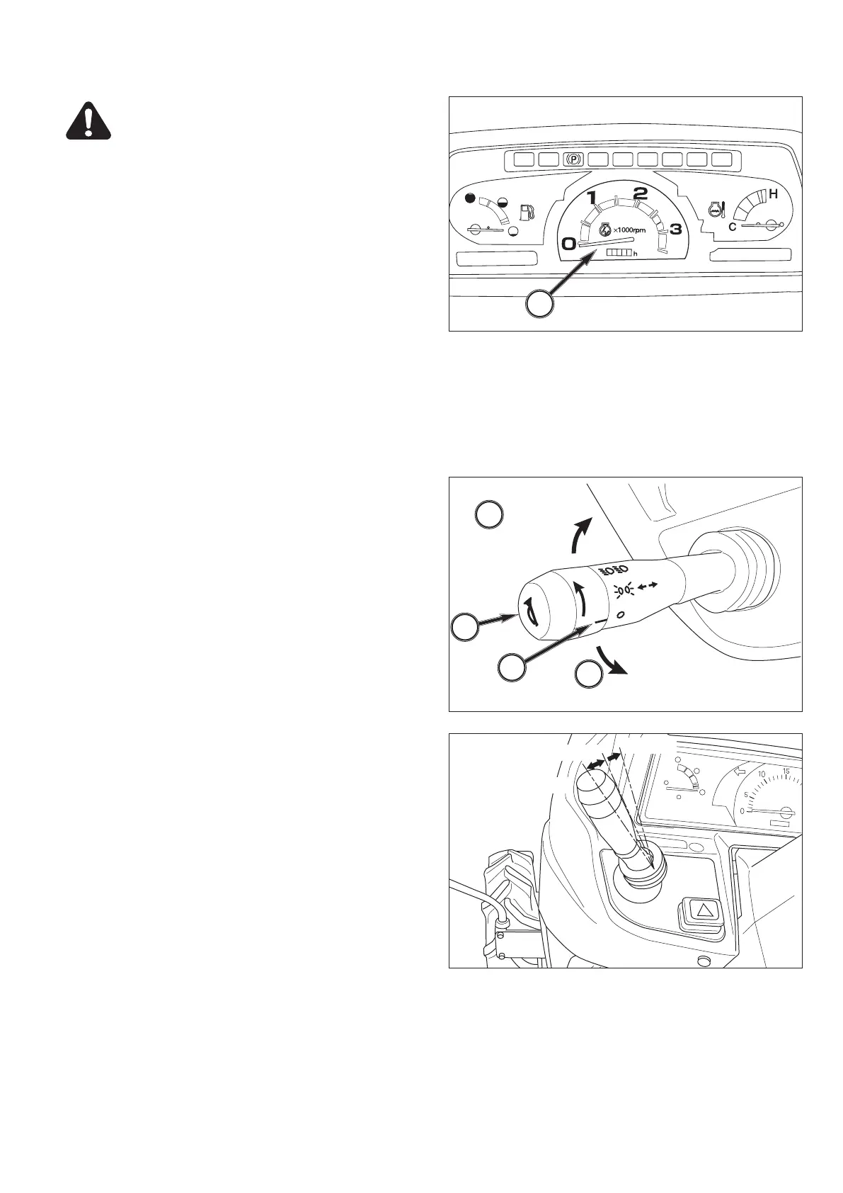
(11) Tachometer
Scale on gauge - Indicates engine speed on crankshaft
revolutions per minutes (min-1).
Index is also provided to show rear PTO speed of 540 at
approximately 2475 engine revolution speed.
Normally, the PTO speed should be between 540 and
600. Operating the PTO at a speed above 600 is too
fast, and may result in a breakdown of the tractor or
implement.
Hourmeter in center of gauge indicates engine and trac-
tor use to assist in maintenance intervals. The extreme
right digit indicates 1 / 10 hour increments.
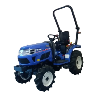
Horn / Light Turn Switch
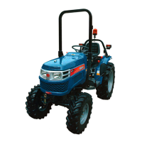
FIGS. 40 & 41: Horn / Light Turn Switch.
Horn Switch, 1 - Horn will sound when center switch
button is depressed.
Light Switch, 2 - Is a rotary switch with 3 operating po-
sitions:
• OFF - Fully counterclockwise. All lights off.
• 1st - Front clearance lamps, rear tail lights, license
plate light and instrument panel illumination.
• 2nd - Main beam headlamps in addition to lamps
lighted at 1st position.
NOTE: High beam / Low beam selection
High beam and low beam are selected by the
position of switch knob.
Middle position: low beam
Down position: high beam
NOTE: Passing switch
Passing switch is turned on when switch knob
is pulled to upward.
NOTE: When high beam is selected (2nd position),
light in indicator light will come on.
Turn Switch, 3 - Operate switch handle in direction
tractor is being turned. The appropriate flashing amber
warning light (ROPS-mounted) will operate as turn sig-
nal. Return switch to center position to cancel.
NOTE: Turn lights will not self-cancel. Select turn /
hazard light switch to center position after com-
pleting turn.
4
g
†
b o
M
l
11
2
1
3
Turn switch RH
1st
2nd
3
Turn switch LH
low beam
high beam
passing
FIG. 39
FIG. 40
FIG. 41



 To Next Page