INSTRUMENTS & CONTROLS
27
INSTRUMENT PANEL AND SWITCHES
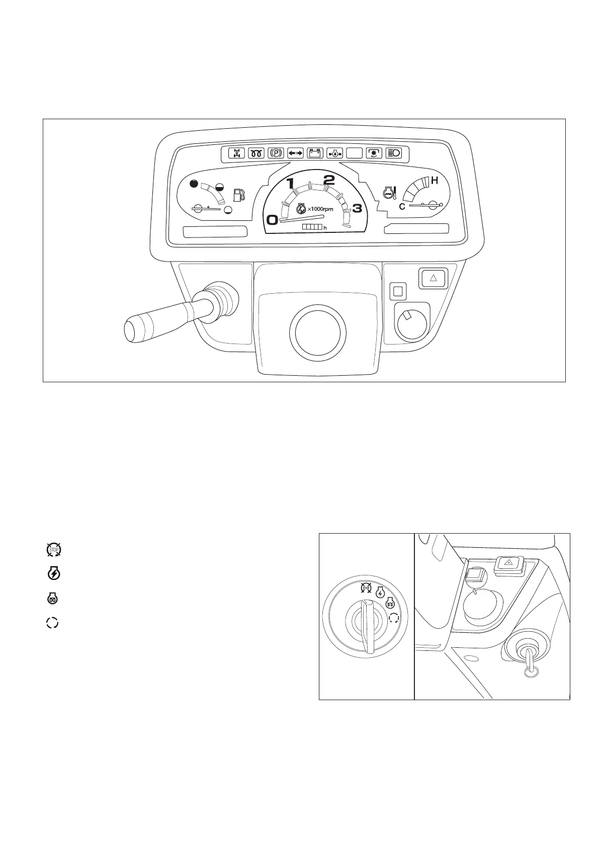
FIG. 36: An arrangement of gauges, control switches and indicators located in instrument panel. Items are detailed in
the description that follows:
Electrical Fuel Shut-Off
Turning the main switch to off will stop the engine.
This tractor is equipped with a solenoid valve, and in case “key” is off position and “solenoid” is off position, the fuel is
shut off.
In case “key” is on position and “solenoid” is on position, the fuel is available.
If electrical malfunction happens, engine stops.
Main Switch
FIG. 37: Main switch, 1, has the 4 following positions:
OFF Engine and all electrical circuits off. Key
can be removed.
ON Power supplied to all circuits. Normal oper-
ating position.
GLOW Energizes glow plugs to preheat the com-
bustion chambers and assist starting.
START Starter activated. This position spring lo-
cated to “ON”.
NOTE: The main switch must be turned to “ON” before
any circuits will operate. The PTO lever (or
switch) must be off and the clutch pedal de-
pressed (Mechanical Transmission) and all gear
shift levers are in neutral before the engine can
be started.
NOTE: When the main switch is selected to “GLOW”
position, the engine combustion chambers will
be preheated and allow a cold engine to be
started after several seconds.
FIG. 36
FIG. 37
 Loading...