TM3215, 3245, 3265
54
1
FIG. 89
3-POINT HITCH
3-point hitch combines the tractor and implement into
1 working unit. Implement positioning and raising are
controlled hydraulically. In addition, implement weight
and loads impose downward pressure to the tractor rear
wheels to increase traction.
Hitch Controls
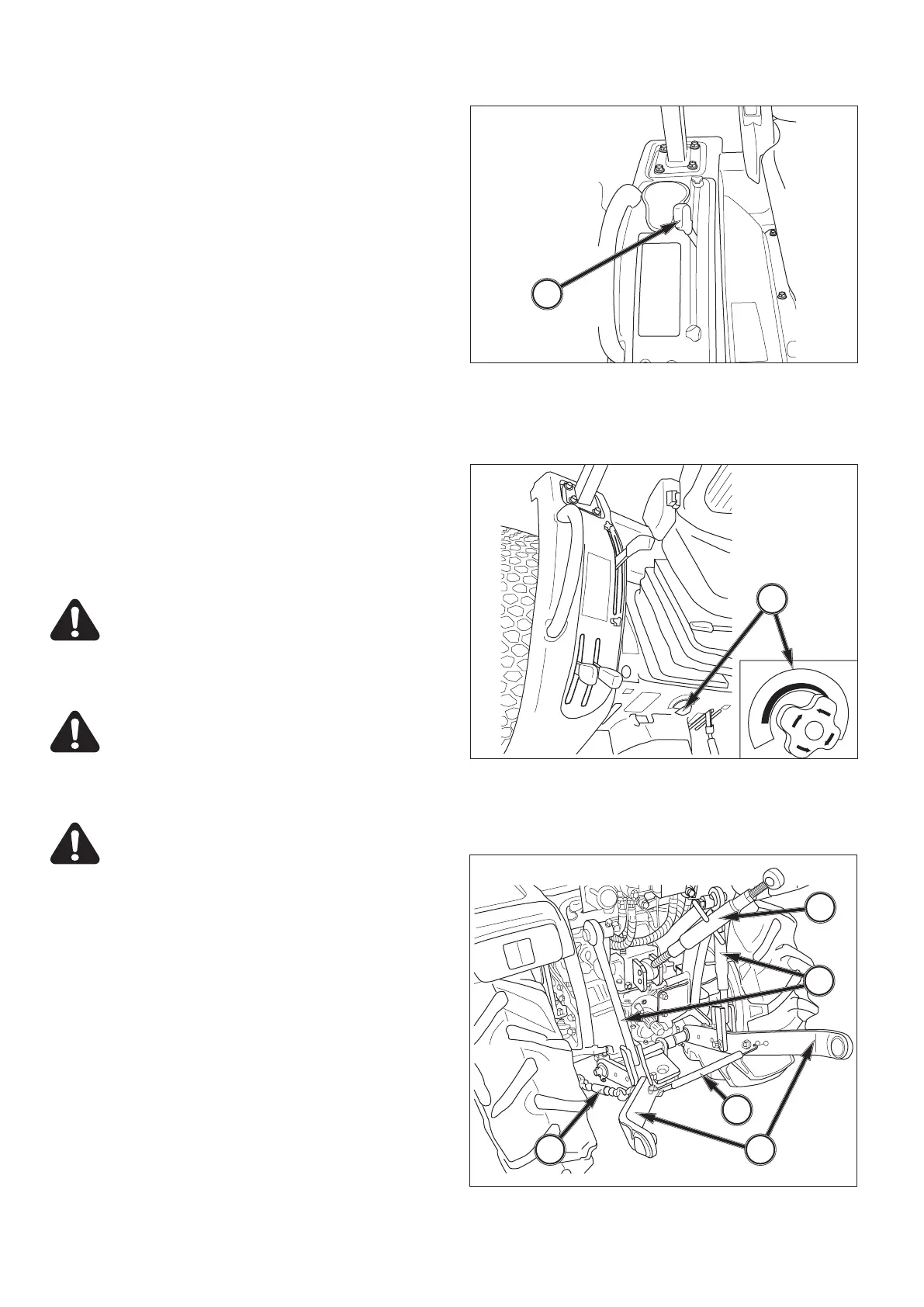
FIG. 89: Control quadrant, to the right of the operator’s
seat, controls the system which provides the following
hitch control functions:
Position Control - Maintains the hitch position at con-
stant height in relation to the tractor. As the position
control lever, 1, is moved rearward, the hitch (and imple-
ment) are raised. Moving the lever forward will lower the
hitch to the selected position. Each lever setting pro-
vides a specific hitch (and implement) position.
FIG. 90: Lowering Rate Control Handle, 2, controls the
discharge rate of hydraulic oil thus adjusting lowering
speed of the hitch and implement. Turn the handle clock-
wise to slow drop rate, counterclockwise to increase
drop rate. Turning the handle fully clockwise will lock the
implement in raised position.
CAUTION: When working on or around
mounted implements, always lower them to
ground prior to work. If an implement must
be raised, always block the implement and
the lower links securely.
CAUTION: Always shut off the PTO and shut
off the tractor engine before servicing any
PTO-driven implement. Allow all movement
and motion to stop before leaving opera-
tor’s seat.
CAUTION: Use the position control lever
when attaching or detaching an implements.
NOTE: When starting the engine, ensure the imple-
ment is lowered to the ground. This reduces
load on the starter due to hitch trying to rise
when the engine is cranked.
Rear Linkage
FIG. 91: Linkage consists of several major components
for implement attachment and operation:
Lower Links, 1 - Primary attaching points to lower im-
plement pins.
Lift Rods, 2 - Connect the lower links to the hydraulic lift
arms for raising / lowering of the lower links. The lift rod
connected to the right lower link has provisions for level-
ing the implement (side to side).
r
t
¨
2
3
4
5
1
2
FIG. 90
FIG. 91



 To Next Page