OPERATION
55
Check Chains, 3 - Reduce side sway of the implement.
Top Link, 4 - Adjustable, turn-buckle type to level imple-
ment (from to rear).
Spring, 5 - Secures the lower links together to prevent
tire interference when the hitch is not used.
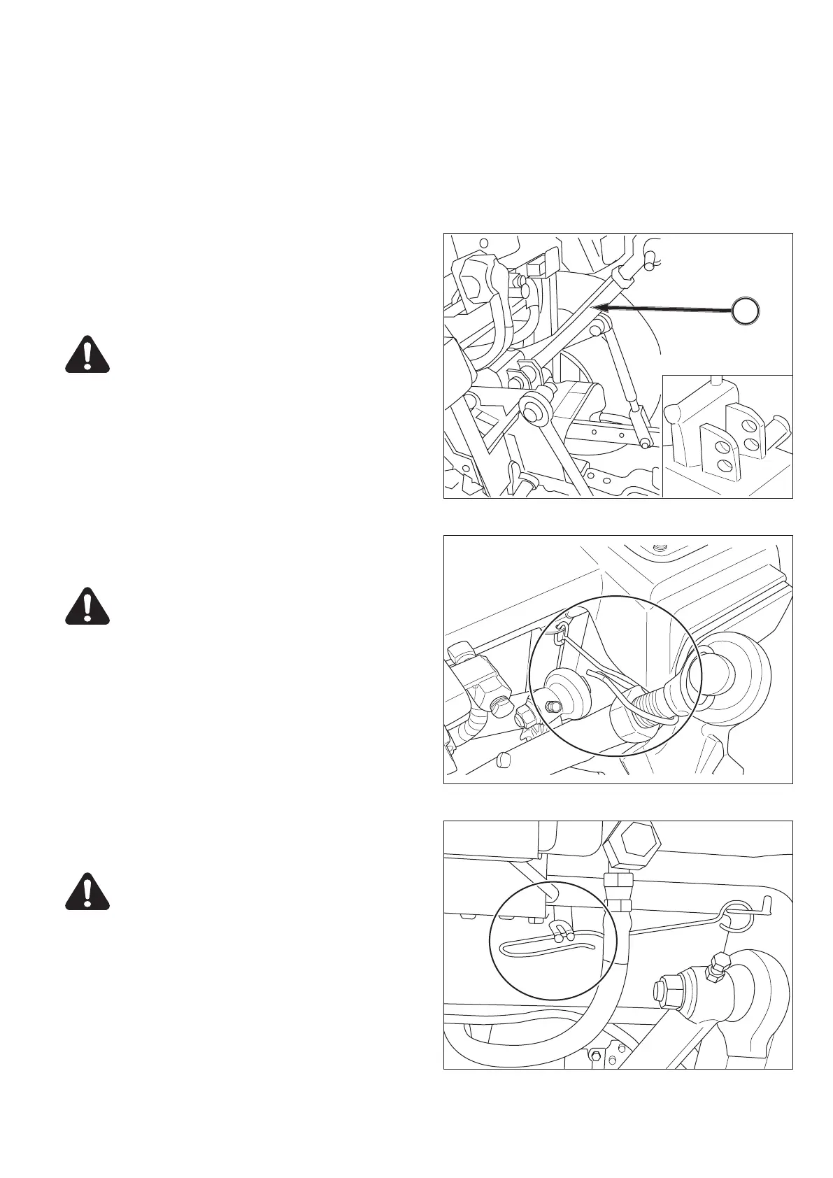
FIG. 92: Linkage provides 2 positions of connecting the
top link, 1, to the tractor.
For most implements, securing the top link, 1, in the up-
per hole A is satisfactory, but position may be varied to
provide increased implement height during transport.
CAUTION: Secure all pins after adjustment
is made. Always use pins supplied with the
tractor.
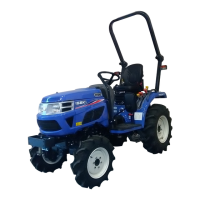
FIG. 93: When top link is not used, fix top link by top link
hook.
CAUTION: Hook on the screw parts of top
link and never interfere with lift rod.
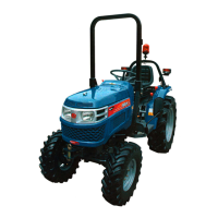
FIG. 94: When top link is used, hold the top link hook by
clamp on frame.
CAUTION: Stay clear from the area of the
3-point linkage when working mounted ma-
chine, trailers and towed machinery.
NOTE: When using implements with PTO shafts, ad-
just the height and width of 3-point to have
clearance between implement and 3-point link-
age. Also check any interference with the mas-
ter shield.
1
FIG. 92
FIG. 93
FIG. 94



 To Next Page