Chapter 4 ELECTRICAL SIGNALS
4-2 UNI-3 Service Manual
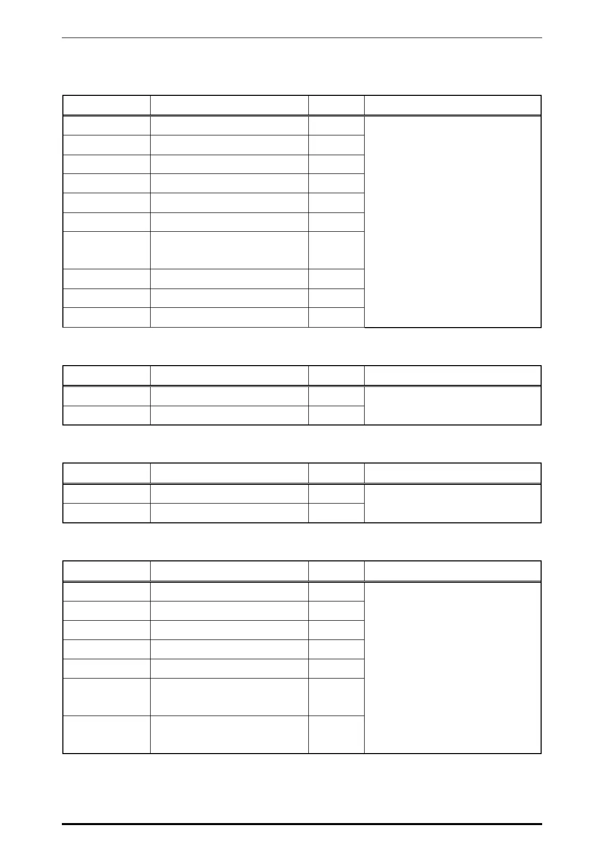
XJ7,8
No. Signal Name Direction Opposite Side
1 GND -
XJ7 : Customer side display (L2)
XJ8 : Operator side display (L2)
2 DC+5V -
3 RESET# ->
4,5,6 E1, E2, E3 ->
7 R/W ->
8 A0 ->
9,10,11,12,13,
14,15,16
LCD data signal
D0 – D7
->
17 LED ANODE (Y/G) -
18,20 Not connected
19 LED CATHODE (Y/G) -
XJ9
No. Signal Name Direction Opposite Side
1 DC+24V -
Back light resister (L2)
2 DC+24V for LCD (L2) -
XJ10
No. Signal Name Direction Opposite Side
1,2,3 DC+24V main power supply -
Switching power supply
4,5,6 GND -
XJ11
No. Signal Name Direction Opposite Side
1 DC+5V -
Thermal head
2 GND -
3,4,6,10,27 Thermal head control signal ->
5,7,8,9,28 Not connected
11,12 Thermistor input signal <-
13,14,15,16,17,
18,19
GND -
20,21,22,23,24,
25,26
DC+24V for thermal head -
 Loading...