Chapter 5 MACHINE DISASSEMBLY
5-10 UNI-3 Service Manual
For the KEY PCB and DISPLAY, refer to the section 5.1.4 CASE COVER BOARD.
* Reverse this procedure for assembly.
5.2.2 NOTE FOR SETUP OF ELEVATED TYPE (L2)
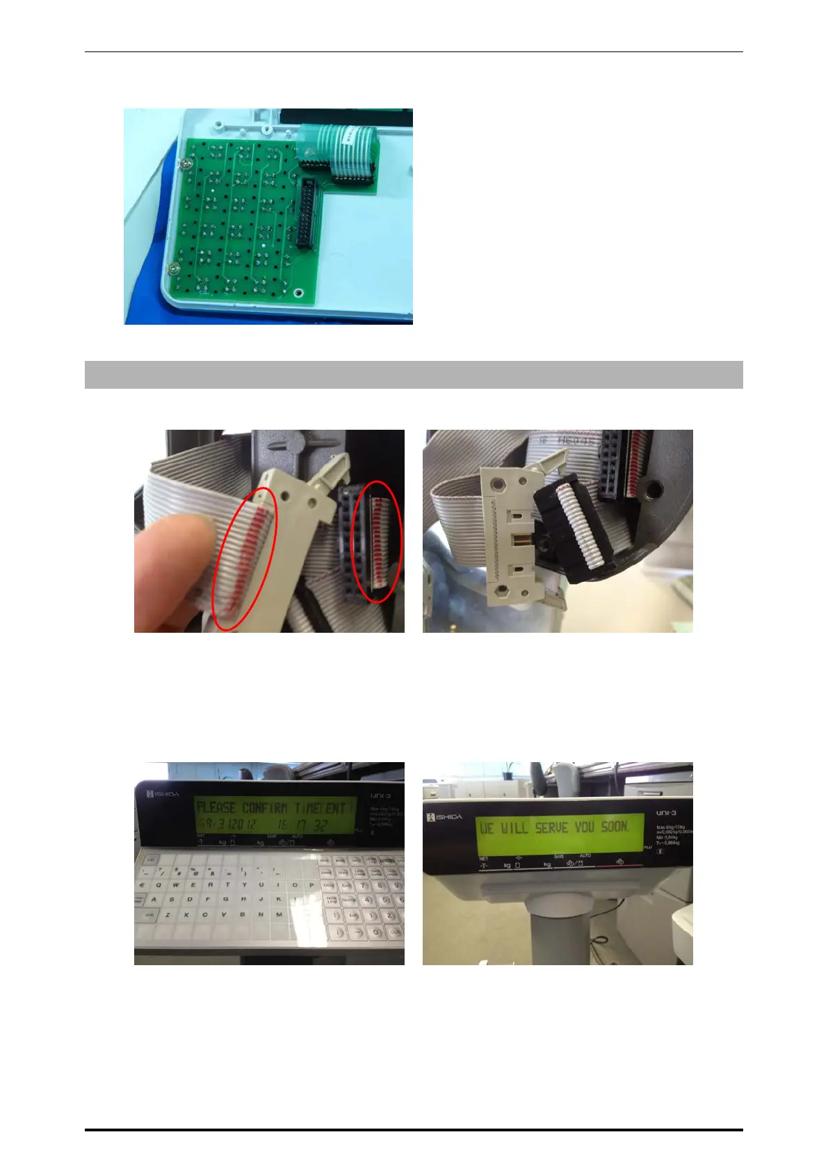
【Harness connection】
Connect the base of elevated operating portion with the base of the body.
Operator side display harness Customer side display harness
The display harness on the operator side has a mark and the display harness on the customer side has no
mark as shown above. Connect the both harnesses that have marks together, and the both harnesses that
have no marks together respectively.
【Display check】
Turn on the power and check the display after completing the connection.
Operator side display Customer side display
When completing the start-up, the date and time is displayed on the operator side display, and the
message “WE WILL SERVE YOU SOON” on the customer side display.
 Loading...