EasyManuals Logo

ISHIDA Uni-3 Service Manual

ISHIDA Uni-3
241 pages
To Next Page IconTo Next Page
To Previous Page IconTo Previous Page
Page #36 background imageLoading...
Page #36 background image
Chapter 4 ELECTRICAL SIGNALS
4-6 UNI-3 Service Manual
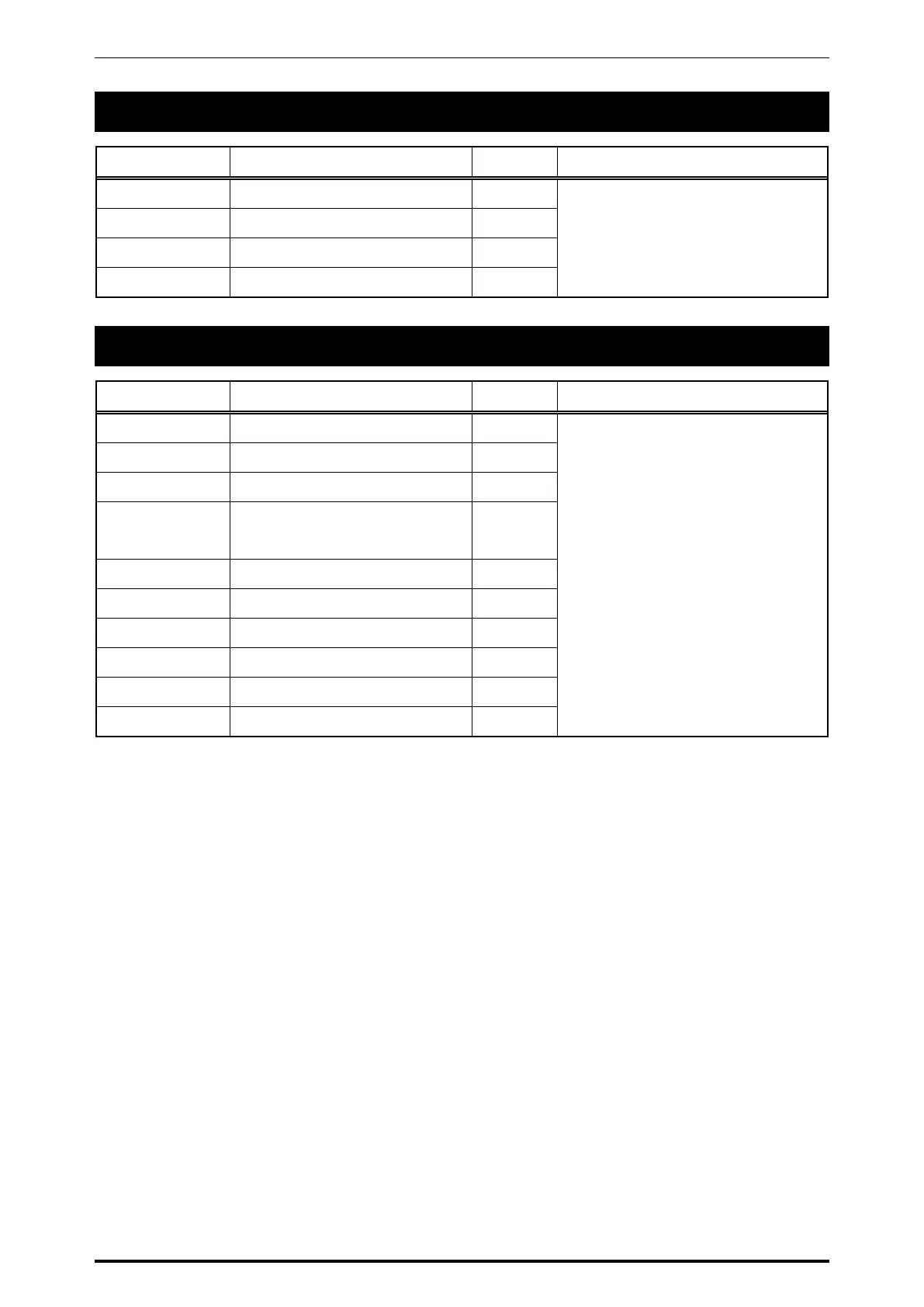
4.4 L1 TYPE LCD DISPLAY BOARD
No. Signal Name Direction Opposite Side
1 DC+5V -
Main board PS-990* XJ19, 20
2 GND -
3,4 LCD control signal <-->
5 DC+5V for LED -
4.5 L2 TYPE LCD DISPLAY BOARD
No. Signal Name Direction Opposite Side
1,3 Not connected
Main board PS-990* XJ7, 8
2 LED CATHODE (Y/G) -
4 LED ANODE (Y/G) -
5,6,7,8,9,
10,11,12
LCD data signal
D0 - D7
<-
13 A0 <-
14 R/W <-
15,16,17 E1, E2, E3 <-
18 RESET# <-
19 DC+5V -
20 GND -

Table of Contents

Other manuals for ISHIDA Uni-3

Questions and Answers:

Question and Answer IconNeed help?

Do you have a question about the ISHIDA Uni-3 and is the answer not in the manual?

ISHIDA Uni-3 Specifications

General IconGeneral
BrandISHIDA
ModelUni-3
CategoryScales
LanguageEnglish

Related product manuals