DAILY MCA2014 4x4 ‒ BODYBUILDER INSTRUCTIONS
ELECTRONIC SUB-SYSTEMS
5.1 ELECTRONIC SYSTEM
5
– Printed 603.95.994 – 1 Ed. - Base 05/2015
ELECTRONIC SUB-SYSTEMS
5.1 ELECTRONIC SYSTEM
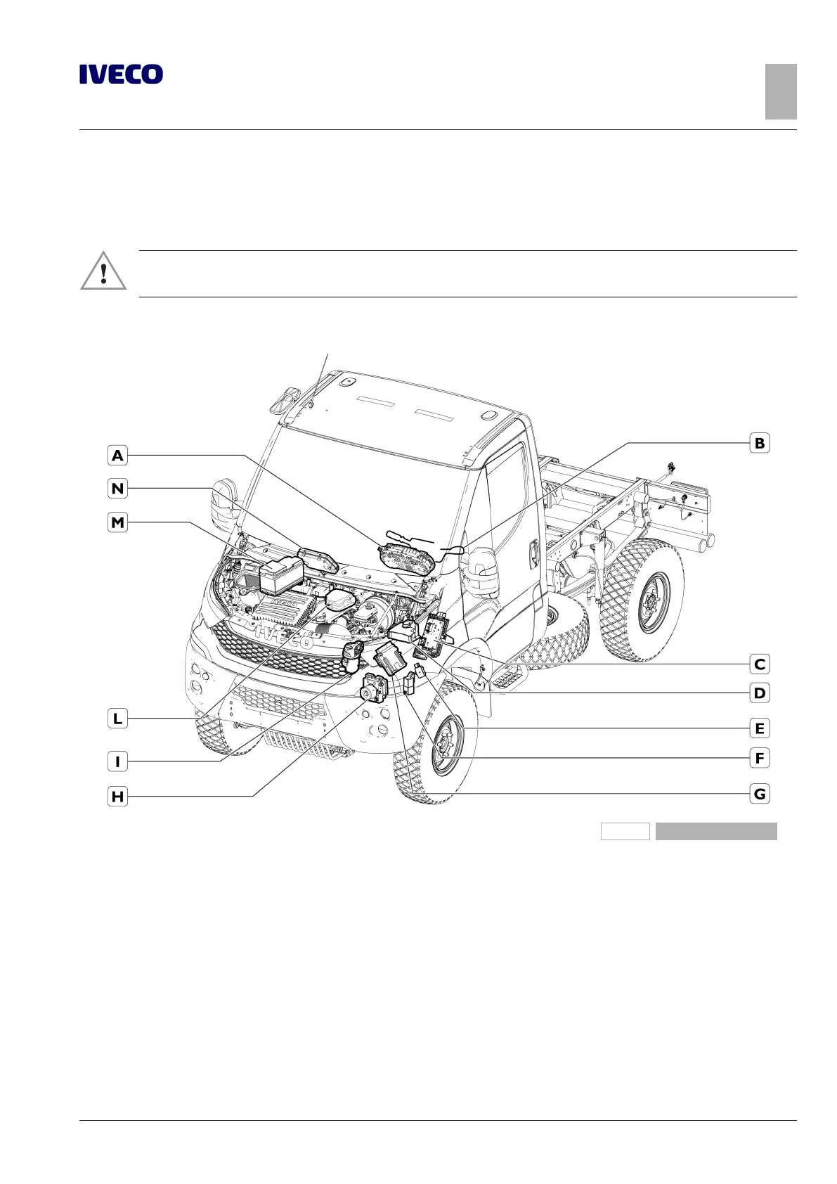
Below is the location of the ECUs and connectors that can be installed on the vehicle.
▶ It is not permitted to connect devices or electrical circuits directly to the control units described
below. Only the connectors listed in the following paragraphs may be used.
Location of control units
228305
Figure 1
A. Instrument panel
B. Steering wheel column and ignition switch
C. Body Computer
D CBA2 control unit in the engine compartment
E. Oil control unit
F. Glow-plugs preheating control unit
G. Engine Management control unit
H. ABS/ESP control unit
I. Green filter
L. SCM connection panel (engine)
M CBA1 control unit on battery
N. Expansion Module

 Loading...
