DAILY MCA2014 4x4 ‒ BODYBUILDER INSTRUCTIONS
ELECTRONIC SUB-SYSTEMS
5.4 ELECTRICAL SYSTEM: CURRENT INTERVENTIONS AND DRAWS
43
– Printed 603.95.994 – 1 Ed. - Base 05/2015
Modifying wheelbase and overhang
Should it be necessary to lengthen the wires on the chassis owing to the new dimensions of wheelbase and overhang, a watertight
junction box must be used which has the same characteristics as those used on the standard vehicle. The electrical components
used such as wires, connectors, terminal blocks, conduits etc. must be of the same type as those used originally and must be cor-
rectly fitted.
As for the functionality of the electronic control devices, junctions are not permitted: the cable must be replaced with a new one
with similar characteristics to the one used on the vehicle and of adequate length.
Trailer setup
If the repetition of rear lights is necessary, the vehicle must be fitted with the 13-pin trailer socket.
Do not hook up directly to the vehicle's light cables. This results in current overloads which are recognised as malfunctions by the
on-board computer.
If the vehicle is not equipped with a trailer socket, it is possible to order a special kit comprising of:
● control unit with fastening bracket and guard;
● chassis cable with trailer configuration;
● rear bridle for trailer socket.
For proper instillation it is necessary to:
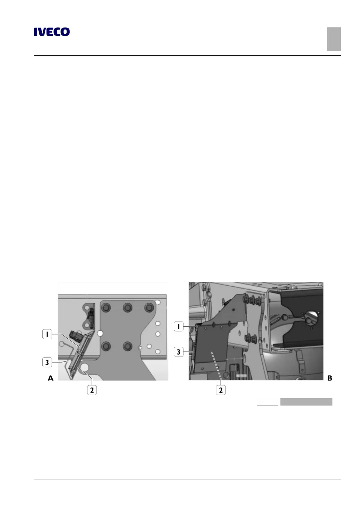
● mount the electronic control unit onto the bracket; on the cab version also mount the guard;
● mount the entire bracket plus control unit onto the chassis as shown in Figure 42;
● replace the chassis cable with the new cable configured for the trailer socket (see Figure 43);
● fit the connection bridle for the 13-pin socket compatible with the type of hook (high or low) (see Figure 44).
209814
Figure 42
A. Side view
B. Rear view
1. Trailer electronic control unit
2. Support bracket
3. Guard

 Loading...
