12
DAILY MCA2014 4x4 ‒ BODYBUILDER INSTRUCTIONS
GENERAL INFORMATION
1.15 DIMENSIONS AND GROUND
– Printed 603.95.994 – 1 Ed. - Base 05/2015
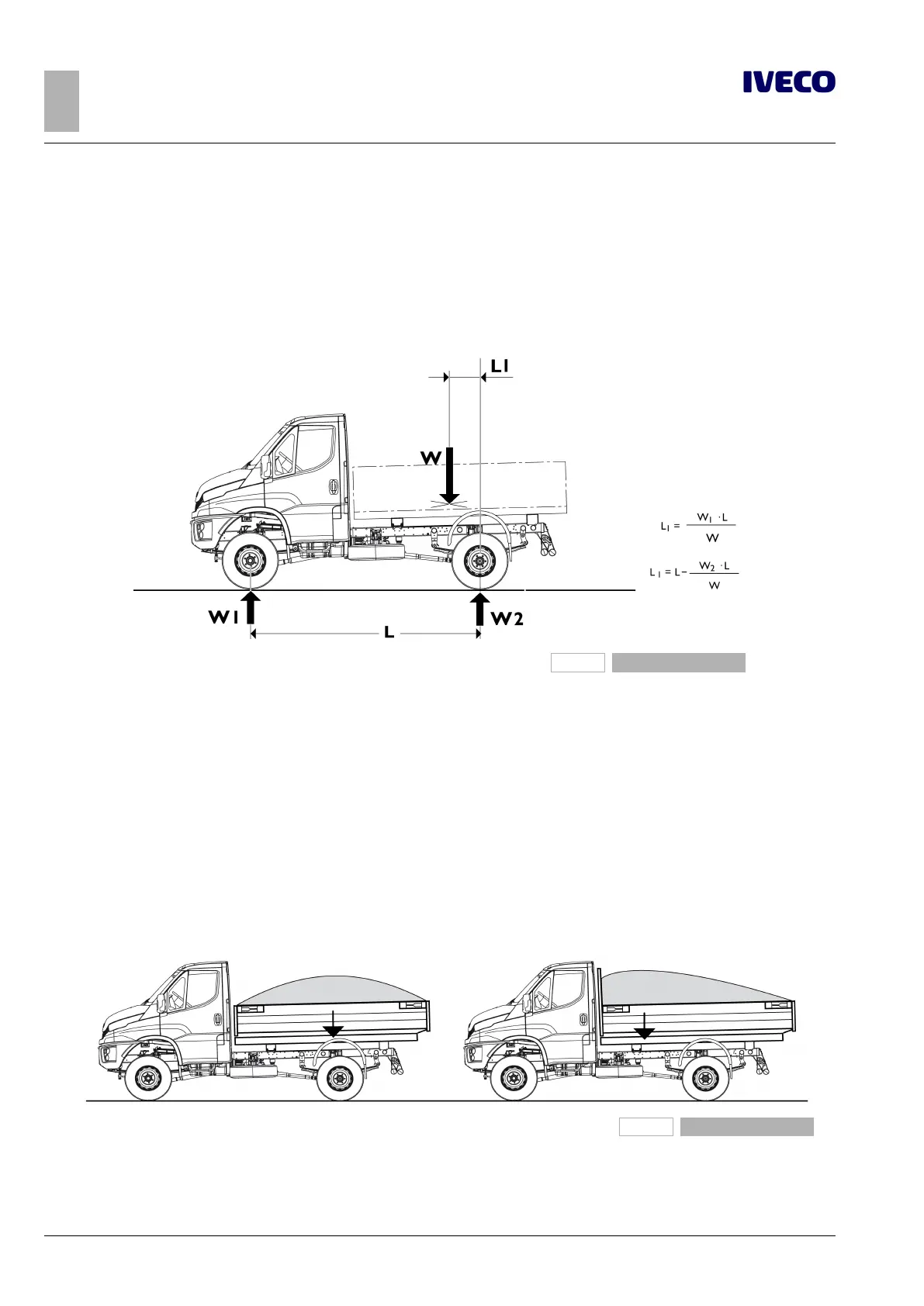
Determination of the centre of gravity of the superstructure and the payload
To determine the position of the centre of gravity of the superstructure and of the payload, proceed according to the following
examples.
The specific technical documentation for each model (cab version diagram) illustrates the positions allowed with the standard ver-
sion vehicle. The masses and the positioning of the individual components of the vehicle are shown on the chassis and weight alloca-
tion diagram.
227313
Figure 3
W = Payload plus superstructure
W1 = Measurement of payload on front axle
W2 = Measurement of payload on rear axle
L1 = Distance of centre of gravity from centre line of rear axle
L = Actual wheelbase
For the purposes of payload distribution on the axles, it is assumed that this is evenly distributed, except in cases in which the shape
of the load surface results in a different load distribution.
For equipment, the centre of gravity is obvious considered for its actual position.
In the realisation of the superstructure or containers, automatic loading and unloading of the goods transported must be provided
to avoid excessive variations of the distribution and/or excessive loads on the axles, providing information for users if necessary.
The Body builder should also provide a suitable anchoring systems for the load on the superstructure, so that transport can occur
in maximum security.
227314
Figure 4
Even distribution of load Uneven distribution of load

 Loading...
