DAILY MCA2014 4x4 ‒ BODYBUILDER INSTRUCTIONS
ELECTRONIC SUB-SYSTEMS
5.4 ELECTRICAL SYSTEM: CURRENT INTERVENTIONS AND DRAWS
29
– Printed 603.95.994 – 1 Ed. - Base 05/2015
Whenever equipment is used which runs on mains power (220 V AC) for its primary or secondary source of power, it must be
checked to ensure that its characteristics are in line with IEC regulations.
Reception/transmission systems
The most frequent applications include:
● amateur receiver-transmitter units for CB (City Band) and 2 m bands.
● GPS receiver and satellite navigation units.
General instructions
1. The equipment must be approved according to the law and be of a fixed nature (not potable).
The use of non approved transmitters or supplementary amplifiers could seriously impede the correct functioning of the
electrical/electronic devices normally supplied, with negative effects for the safety of the vehicle and/or the driver.
2. The system already provided on the vehicle must be used to power the transmitters and they must be connected to terminal
K30 of the connector ST40 (and K15 where necessary) via a supplementary fuse.
Any additional power lines must be created respecting the correct sizing of cables and protection.
3. The coaxial antenna cable must be positioned taking care to:
■ use a low loss, top quality product with the same impedance as the transmitter and the antenna (see Figure 29);
■ in order to avoid interference and malfunctioning, create a path (the shortest possible) which maintains a suitable dis-
tance (min. 50 mm) from pre-existing cabling or from other cables (radio, amplifiers and other electronic equipment),
keeping the minimum distance from the metal structure of the cab and using existing holes in the sheet metal;
■ do not shorten or lengthen; avoid unnecessary tangles, tension, folds and crushing.
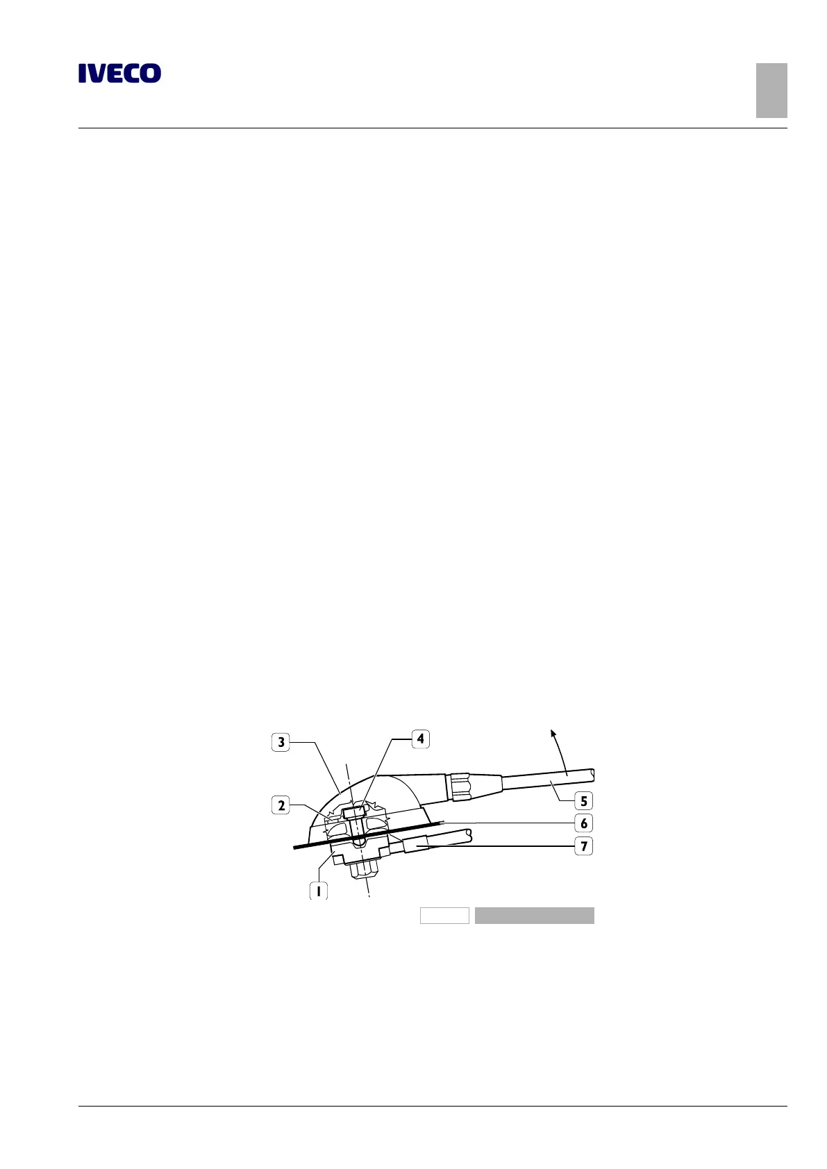
4. Outside the cab, the antenna must be installed on the vehicle on a metal base with a wide surface; it must also be fitted as ver-
tically as possible with the connection cable pointing downwards and, in any case, following the manufacturer's fitting instruc-
tions and warnings (see Figure 28).
Installation at the centre of the roof is to be considered the absolute best as the ground plane is proportional in all directions.
Inside the cab, the transmitter equipment must be positioned as shown in Figure 30.
5. The quality of the antenna, the mounting position and a perfect connection to the vehicle structure (ground) are factors of
fundamental importance to guarantee the best performance of the transmitter equipment.
98915
Figure 28
1. Antenna support
2. Gasket
3. Fixed joint cover
4. Fastening screw M6x8.5 (tighten to a tightening torque of
2 Nm)
5. Aerial
6. Roof panel
7. Antenna extension cable

 Loading...
