8
DAILY MCA2014 4x4 ‒ BODYBUILDER INSTRUCTIONS
APPLICATIONS OF SUPERSTRUCTURES
3.2 ELEMENTS MAKING UP THE COUNTER CHASSIS
– Printed 603.95.994 – 1 Ed. - Base 05/2015
3.2 ELEMENTS MAKING UP THE COUNTER CHASSIS
Longitudinal profiles
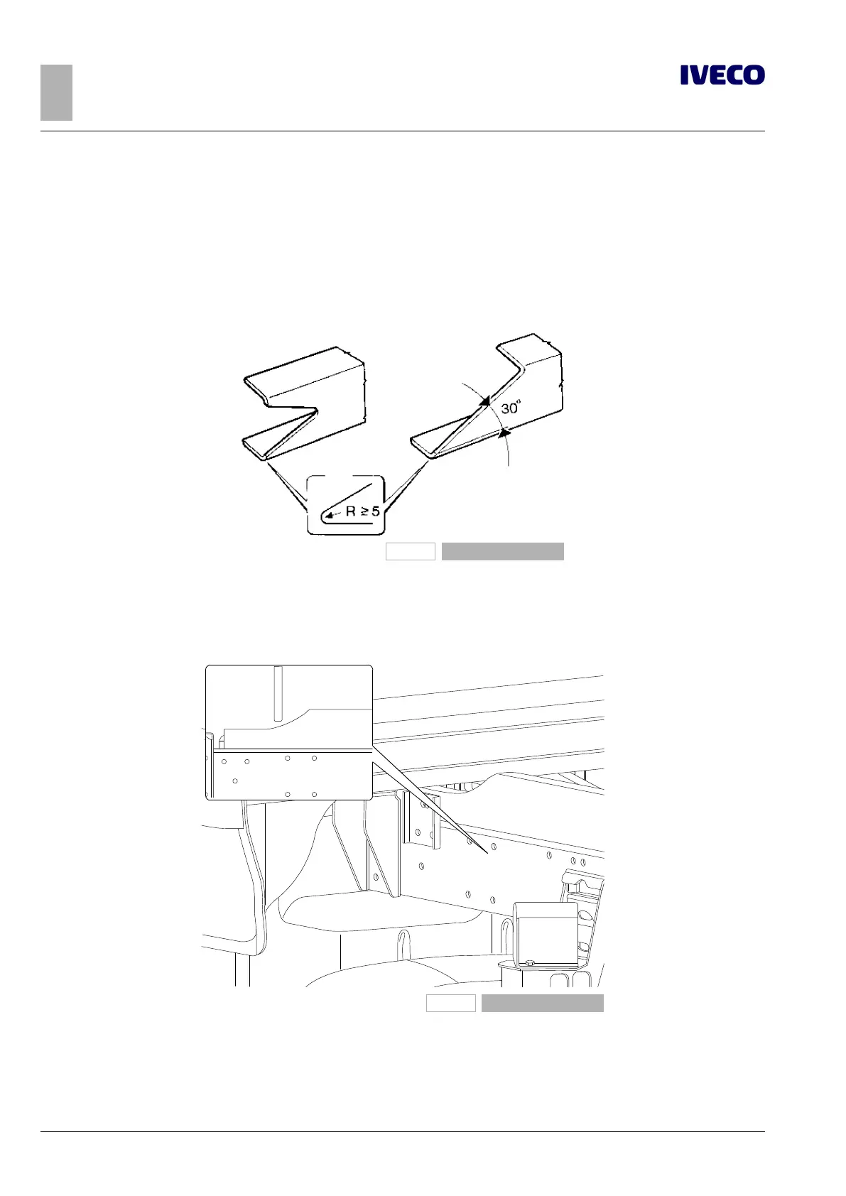
The side members of the added structure must be continuous, extended as much as possible toward the front of the vehicle and
towards the rear area of the front spring support; in addition, they must rest on the chassis and not on the brackets.
In order to achieve a gradual reduction of the resistant section, the front ends of the profile must be tapered in height with an
angle not exceeding 30°, or another form of equivalent tapering (see Figure 2); the front end in contact with the chassis must be
properly coupled, with min. radius of 5 mm.
91136
Figure 2
In cases in which the components of the cab rear suspension (e.g. deep cabs) do not allow the passage of the profile in the entire
section, this can be realised as in Figure 3. This may require verification of the minimum section of resistance in the presence of high
front bending moments (e.g. with a crane behind the cab when operating towards the front of the vehicle) and requires fixing if
possible at no more than 250 mm from the front end of the sub-chassis.
120370
Figure 3
The shape of the profile section is defined taking into account the function of the counter chassis and the type of overlying struc-
ture. Open C profiles are advisable when the counter chassis needs to adapt elastically to the vehicle chassis and boxed sections
when you require greater stiffness of the assembly.
Care should be taken to achieve a gradual transition from the boxed section to the open section, as in the examples in Figure 4.

 Loading...
