14
DAILY MCA2014 4x4 ‒ BODYBUILDER INSTRUCTIONS
APPLICATIONS OF SUPERSTRUCTURES
3.3 CONNECTION BETWEEN CHASSIS AND COUNTER CHASSIS
– Printed 603.95.994 – 1 Ed. - Base 05/2015
2. In versions where the vehicle is lifted by hydraulic stabilisers (e.g. cranes, overhead work platforms), limit the collapse of the
elastic element to ensure sufficient cooperation of the counter chassis and avoid excessive bending moments on the original
chassis.
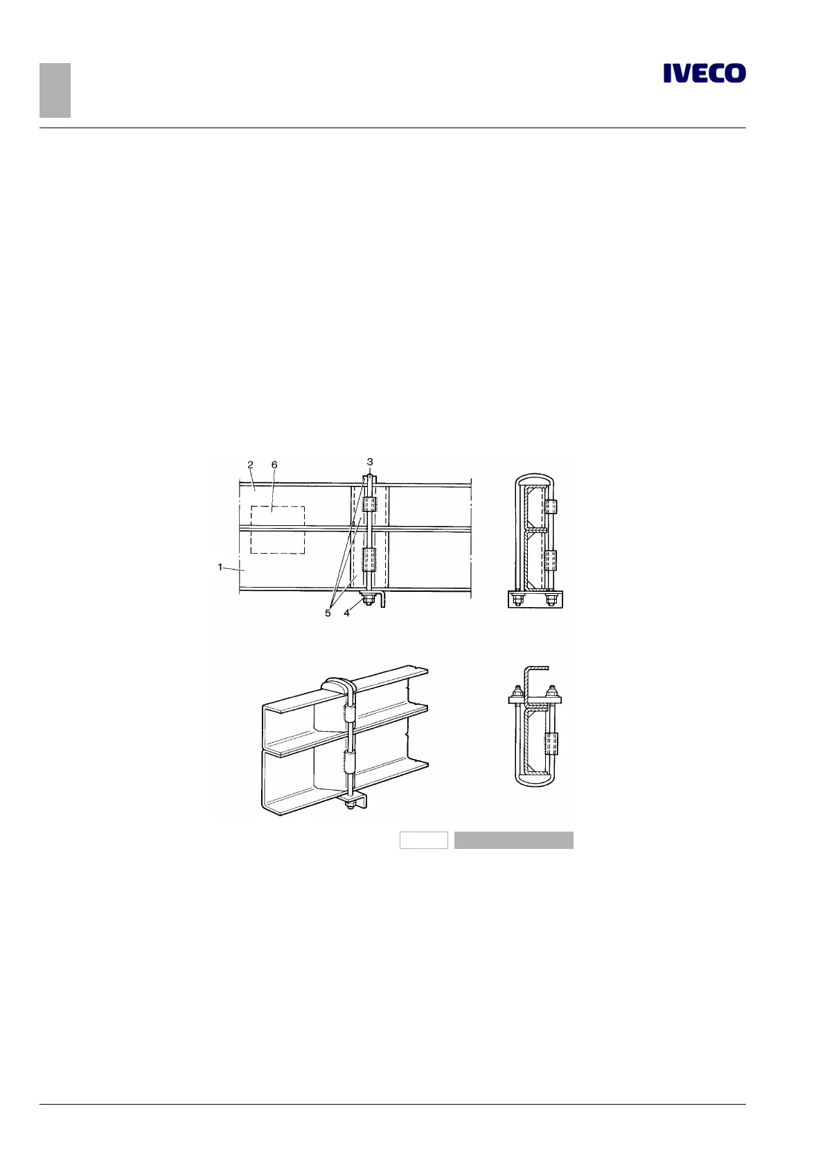
Connections with clevis fasteners or clamps
Figure 10 shows the main constructions of this type.
In this case the Body builder must interpose a spacer (preferably metal) between the wings of the two side members and in corres-
pondence to the clevis fasteners, in order to avoid the bending of the wings under the pull of the clevis fasteners.
In order to drive and better contain the transverse direction of the structure added to the chassis, this type of fixing can be com-
pleted with the addition of plates welded to the counter chassis as shown in Figure 11.
The characteristics of this connection advise against a general integral use on the vehicle; in any case, to give the added structure the
suitable containment in the longitudinal direction as well as adequate stiffness, it is necessary to integrate the fastening to the rear
part with longitudinal and transverse sealing plates.
193873a
Figure 10
1. Chassis
2. Counter chassis
3. Clevis fasteners
4. Closure with anti-unscrewing system
5. Spacers
6. Guide plates (if necessary)

 Loading...
