24
DAILY MCA2014 4x4 ‒ BODYBUILDER INSTRUCTIONS
APPLICATIONS OF SUPERSTRUCTURES
3.9 INSTALLATION OF TAIL LIFTS
– Printed 603.95.994 – 1 Ed. - Base 05/2015
3.9 INSTALLATION OF TAIL LIFTS
Note
The installation of tail lifts must be carried out with due regard for the maximum permissible weights on the rear axles of the
vehicle and of the minimum load established for the front axle (see Chapter 1.15 (
➠
Page 28)). If this is not possible, the rear
overhang will have to be reduced.
The tail lift must be fastened with a structure that ensures appropriate weight distribution, especially in the case of specific outfits
with no adequate counter chassis (e.g. box truck bodies, pick-up bodies with cross-members).
The dimensions of the sections to be used can be defined:
● using Table 3.8, in the presence of trucks with rear overhangs as standard;
● using the specifications of Figure 20, in the presence of trucks with non-standard overhangs or specific tail lifts (eg. aluminium)
and noting that the flexing moments on the chassis, depending on the board capacities, must be calculated each time;
● using assessments to be carried out each time, in the case of vans, when tail lifts with capacities exceeding 3 kN (300 kg) are
used.
To ensure the necessary strength and rigidity, and especially in the case of overhangs exceeding 1200 mm, the connection between
the chassis and the counter chassis must be made using shear-resistant plates (spaced no further than 400 mm from one another)
in the area of the rear overhang, and must continue up to the front support of the rear suspension (see Figure 20).
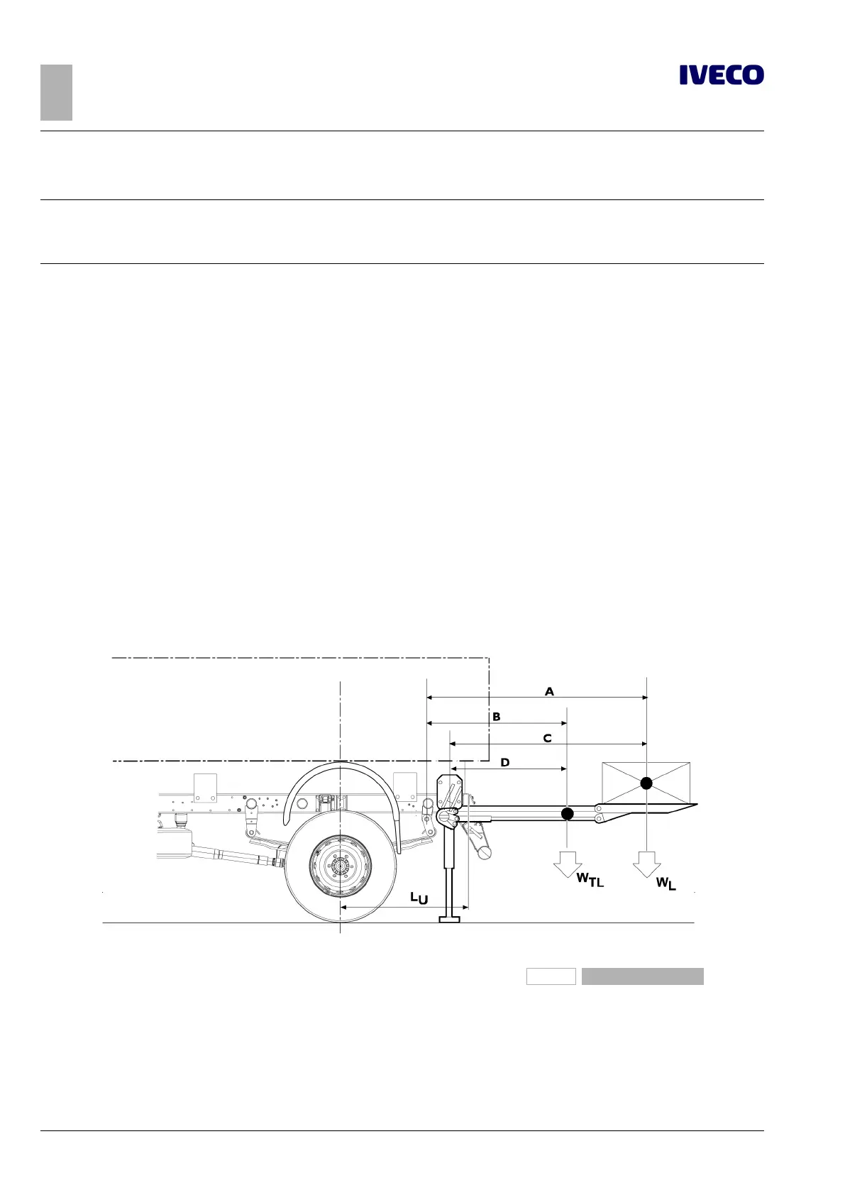
Procedure for calculating the chassis bending moment during loading of tail lift
230047
Figure 20
W
TL
= Weight of tail lift
W
L
= Tail lift capacity
The bending moment on the chassis may be obtained using the following ratio:
M [Nm] = W
L
• A + W
TL
• B for tail lifts without stabilisers

 Loading...
