DAILY MCA2014 4x4 ‒ BODYBUILDER INSTRUCTIONS
APPLICATIONS OF SUPERSTRUCTURES
3.8 INSTALLING A CRANE
23
– Printed 603.95.994 – 1 Ed. - Base 05/2015
228304
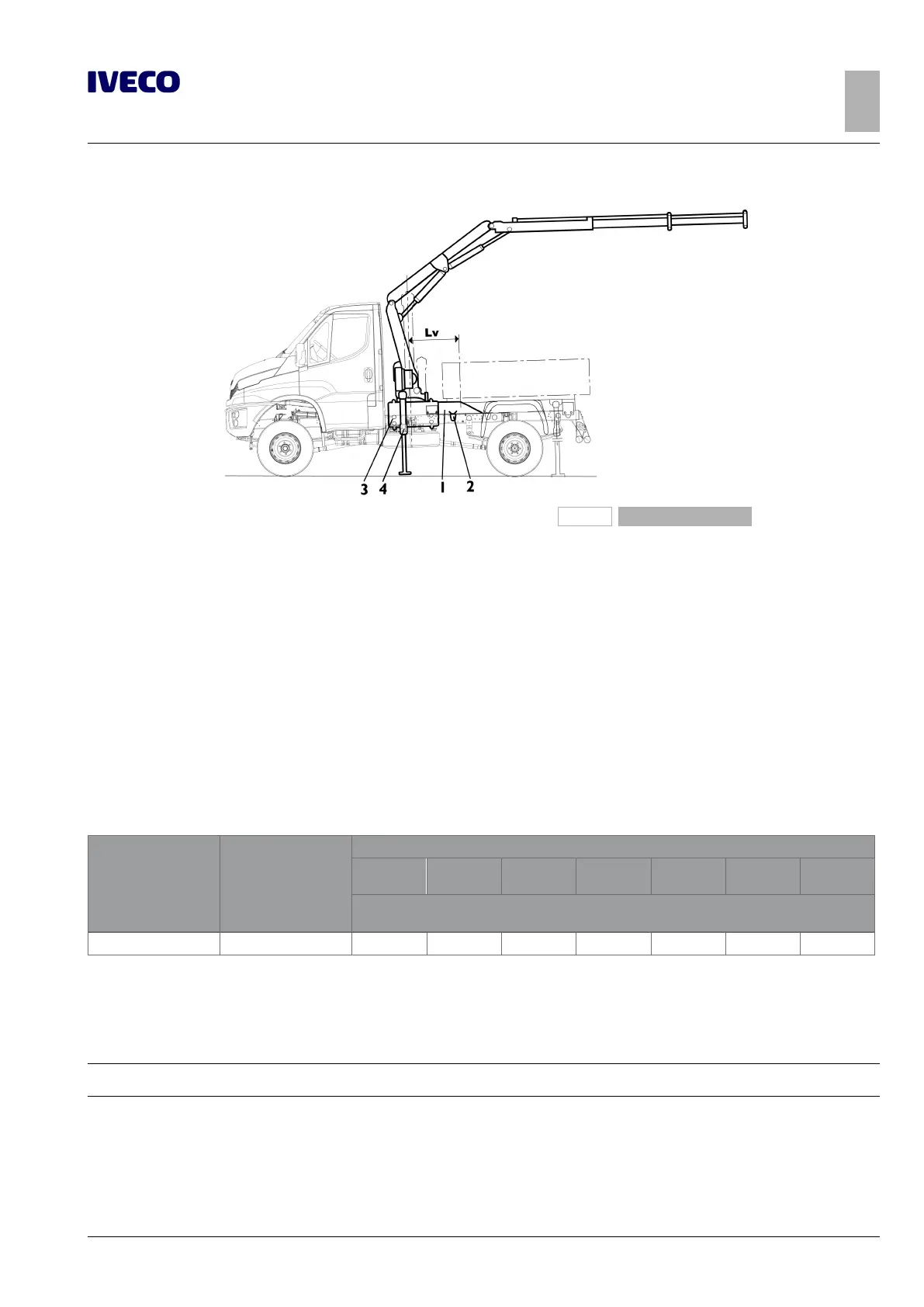
Figure 19
1. Reinforcing profile
2. Brackets
3. Crane connections
4. Stabilisers
In installations of cranes on vehicles with deep cab (e.g. 6 +1), the counter chassis must continue to underneath the cab (see Figure
2), otherwise, depending on the capacity of the crane, it will be necessary to limit the crane's range of rotation, so as not to exceed
the permissible bending moment from the chassis.
Elastic connections between chassis and counter chassis (see Figure 8) may be needed to avoid excessive constraint on the chassis
torsional movement for application of crane on off-road vehicles on the front and middle parts. The crane is practically connected
to the counter chassis only, the dimensions of the longitudinal sections must therefore be suited to withstand the moment induced
during use.
The container or equipment must normally be retracted to arrange the crane behind the cab. In the specific case of tipping equip-
ment, particular attention must be paid to arranging the mounts of the lifting device and the tipper rear hinges which must be as
retracted as possible.
Table 3.7 - Crane behind driver's cab (counter chassis secured with shelves or flanges)
Model
Wheelbase
[mm]
Total torque M
G
max [kNm]
20
20
30
30
40
40
50
50
60
60
70
70
80
Minimum value of the section modulus of the counter chassis section W
x
[cm
3
]
(1)
with yield point of the material equal to 360 N/mm
2
35S15/17, 55S15/17 3050, 3400 21 36 57 89 E E E
Close the reinforcement section in the crane assembly area.
E = To be checked case-by-case. Send IVECO technical documentation with verification of stress and stability.
(1)
When a higher modulus of resistance is required for the superstructure also use the latter for the crane.
Note
For the dimensions of the profiles see Table 3.2.

 Loading...
