DAILY MCA2014 4x4 ‒ BODYBUILDER INSTRUCTIONS
APPLICATIONS OF SUPERSTRUCTURES
3.1 CONSTRUCTION OF THE COUNTER CHASSIS
5
– Printed 603.95.994 – 1 Ed. - Base 05/2015
APPLICATIONS OF SUPERSTRUCTURES
Note The following specific instructions complement the regulations contained in Section 1 “GENERAL INFORMATION”.
3.1 CONSTRUCTION OF THE COUNTER CHASSIS
The purpose of the counter chassis is to ensure a uniform load distribution on the vehicle chassis and the necessary cooperation
with it to the effects of resistance and stiffness, depending on the vehicle's specific use.
Material
In general, if the stresses on the counter chassis are not high, the material for its realisation may have characteristics inferior to
those of the frame, notwithstanding the need to have good characteristics of weldability and limits that are not lower than the val-
ues (1) shown in Table 3.1.
In cases where the stress limits require it (e.g. for crane applications), or if you want to avoid high section height, materials with
superior mechanical characteristics may be used. You should, however, keep in mind that the reduction of the time of inertia of
the reinforcing section involves bending and higher stresses on the main chassis.
Following are the characteristics of certain materials which were taken into account in some of the applications stated below.
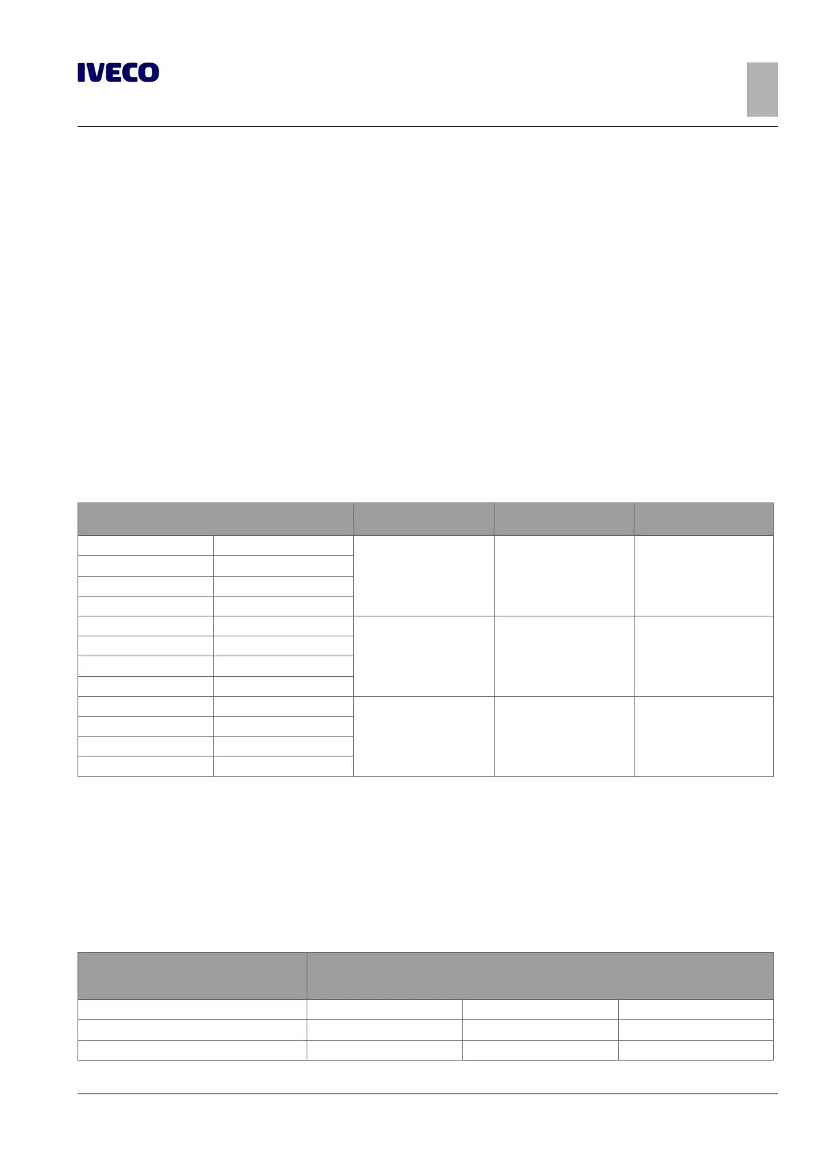
Table 3.1 - Material to be used for the construction of superstructures Std IVECO 15-2110 and 15-2812
Name of steel
Breaking strength
[N/mm
2
]
Yield stress
[N/mm
2
]
Elongation
IVECO Fe 360D
360 (1) 235 (1) 25% (1)
EUROPE S235J2G3
GERMANY ST37-3N
U.K. 40D
IVECO Fe E420
530 420 21%
EUROPE S420MC
GERMANY QStE420TM
U.K. 50F45
IVECO Fe 510D
520 360 22%
EUROPE S355J2G3
GERMANY ST52-3N
U.K. 50D
Sizing of profiles
The following table shows the values of resistance modulus W
x
for C section profiles recommended by IVECO.
The indicated value W
x
refers to the actual section and takes into account the radii of curvature of the section (can be calculated
with good approximation by multiplying the value obtained by 0.95 considering the section composed of simple rectangles). Profiles
of different section may be used in lieu of those specified, provided that resistance modulus W
x
and inertia time J
x
of the new C
section are not of a lesser value.
Table 3.2 - Profile dimensions
Resistance modulus W
x
[cm
3
]
Recommended C profile
[mm]
16 ≤ W ≤ 19 80 X 50 X 4 80 X 60 X 4 80 X 50 X 5
20 ≤ W ≤ 23 80 X 60 X 5
24 ≤ W ≤ 26 80 X 60 X 6

 Loading...
