DAILY MCA2014 4x4 ‒ BODYBUILDER INSTRUCTIONS
APPLICATIONS OF SUPERSTRUCTURES
3.8 INSTALLING A CRANE
21
– Printed 603.95.994 – 1 Ed. - Base 05/2015
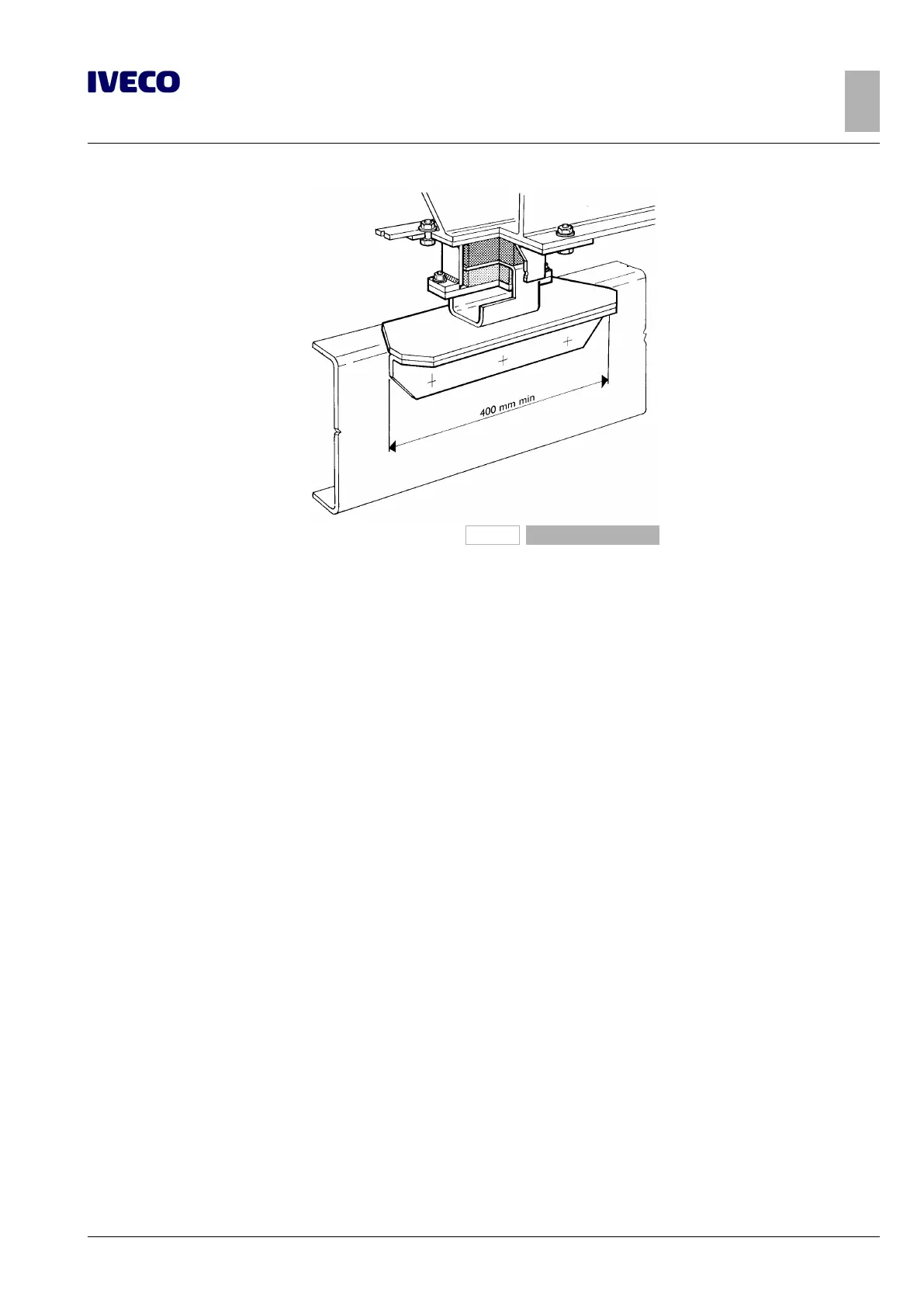
208921
Figure 17
The maximum volume, the degree of filling of the container and the volumetric mass of the transported goods must be defined
in observance of the axle weight limits. In the case of tanks and single containers made with separate compartments, the minimum
ratio between front axle weight and total fully loaded weight (see Chapter 1.15 ( ➠ Page 11)) as well as the maximum axle loads
must be observed for all loading conditions.
In consideration of the type of outfit, the use of vehicles equipped with stabilizer bars is recommended and particular attention
should be paid to limiting, as far as possible, the height of the overall centre of gravity (see Chapter 1.15 ( ➠ Page 11)); use of a
vehicle with stabiliser bars is recommended.
In tanks and containers for liquids, transversal and longitudinal partitions are to be used in. In fact, if these are not completely full,
the dynamic thrust which the liquid generates while the vehicle is in motion could negatively influence the vehicle's handling and
resistance.
Follow the safety laws in force (see Chapter 2.18 ( ➠ Page 34)) for containers intended to carry flammable liquids.
3.8 INSTALLING A CRANE
The selection of the crane must be made with due consideration to its characteristics and in relation to the performance of the
vehicle.
The positioning of the crane and of the payload must be done within the load limits permitted for the vehicle. Installation of the
crane must be carried out in compliance with statutory requirements, national standards (e.g. CUNA, DIN) and international stand-
ards (e.g. ISO, CEN) and verifying those required for the vehicle.
While the crane is operating, the stabilisers (hydraulic if possible) must be used and be in contact with the ground.
As a general rule, the installation of a crane requires the use of a suitable counter chassis, the construction of which must take into
account the general specifications (see Chapter 3.1 ( ➠ Page 5)) and with the dimensions of the sections given in Table 3.7.
The dimensions of the counter chassis resistance modulus refer to the maximum total static moment of the crane (M
G
), deduced
from the formula shown in Figure 18.
If the vehicle outfitting requires the use of a section with modulus resistance greater than that required for the crane (e.g. tipper),
this section may also be considered for the crane.
Special cases in which the moment M
G
values correspond to the “E” value in the Table (or for higher values) must be checked
individually each time and must receive specific authorisation from IVECO.

 Loading...
