44
DAILY MCA2014 4x4 ‒ BODYBUILDER INSTRUCTIONS
ELECTRONIC SUB-SYSTEMS
5.4 ELECTRICAL SYSTEM: CURRENT INTERVENTIONS AND DRAWS
– Printed 603.95.994 – 1 Ed. - Base 05/2015
209816
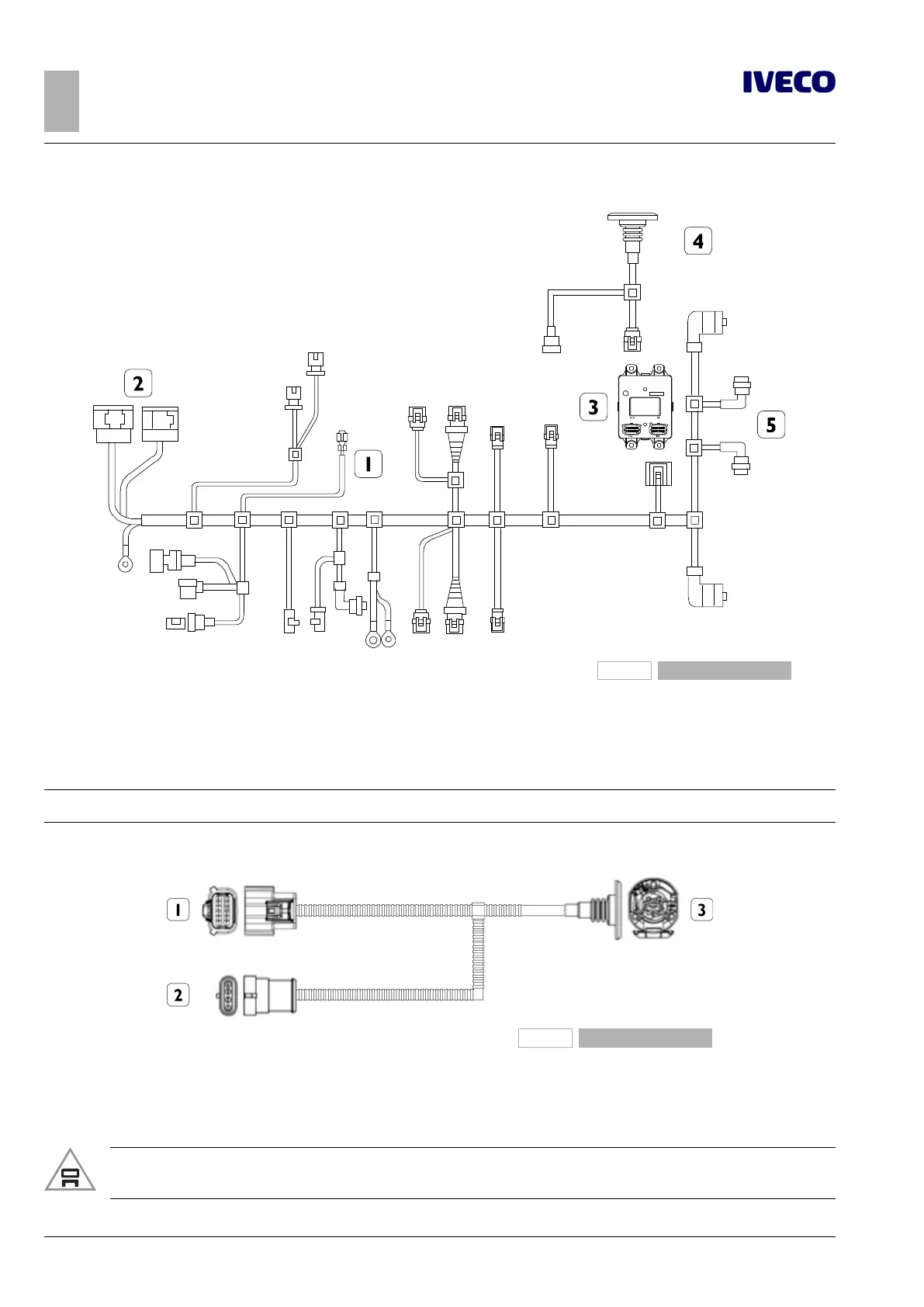
Figure 43
Chassis cable with 13 pin socket and trailer control unit
1. Chassis cable
2. Connections with cab wiring
3. Trailer electronic control unit
4. 13-pin trailer socket
5. Tail lights
Note
The graphic is for illustration purposes only.
209815
Figure 44
1. Connector 86046_1 to connect to connector 1 (OUT) of
trailer control unit
2. Connector ST63 to connect to chassis wiring
3. 13-pin trailer socket 72016
For further details on connections and installation, request wiring diagrams from IVECO.
▶ Any damage to the light system caused by failure to comply with procedure is not covered by
warranty.

 Loading...
