DAILY MCA2014 4x4 ‒ BODYBUILDER INSTRUCTIONS
CHASSIS INTERVENTIONS
2.15 WORK ON THE BRAKING SYSTEM
29
– Printed 603.95.994 – 1 Ed. - Base 05/2015
Preparation and assembly (IVECO STD 17-2403)
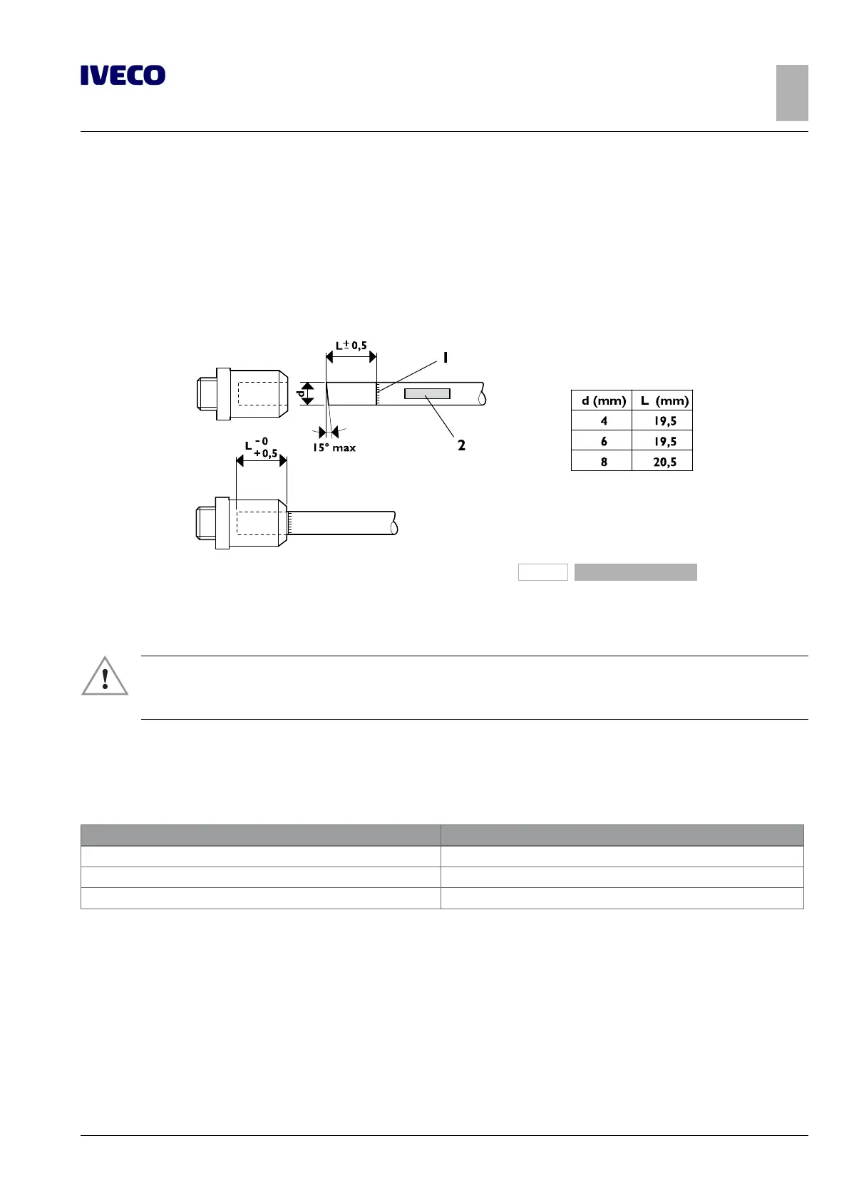
Cut the pipe at right angles (15° maximum error), using a special tool in order to avoid imperfections that affect the sealing.
Permanently mark the section of pipe (dimension L in Figure 9) to be inserted into the coupling to ensure secure sealing.
Mark the pipe to avoid assembly errors in case of subsequent repair operations.
As much as possible, use the same couplings as the original ones, or otherwise belonging to the normal production of specialised
manufacturers in the sector.
208209
Figure 9
1. Identification of pipe limit 2. Marking
As much as possible, use quick-fit couplings.
▶ For each intervention on the piping, verify whether there is the need, depending on the supplier,
to use always new couplings or if it is possible to reuse those originally present through the use of
appropriate tools (pliers).
When the space conditions require it (e.g. in proximity of curves), couplings with metal inserts can be used.
Before inserting the pipe into the coupling, screw the coupling into the threaded insert of the same component (e.g. pneumatic
valve), using the following values for tightening:
Table 2.12
Thread Tightening torque [Nm ± 10%]
M 8 x 1 mm 20
M 12 x 1.5 mm 24
M 14 x 1.5 mm 28
Insert the pipe into the coupling for the previously marked stretch of length L, using a force of between 30 and 120 N, depending
on the size of the tube.
The replacement of components (valves, etc..) is made possible because the engagement and coupling allow an internal rotation
during the operation of unscrewing and screwing.

 Loading...
