www.janitza.com UMG 804
43
10. Voltage Input /
Electrical Connections
DANGER
HAZARD OF ELECTRIC SHOCK,
EXPLOSION, OR ARC FLASH
· While removing or installing panels and
covers, assure that they do not contact an
energized bus.
· NEVER bypass external fusing.
· NEVER short the secondary of a potential
transformer.
· Before closing covers and doors, carefully
inspect the work area and remove any tools,
wire scraps or other objects that may have
been left inside the equipment.
Failure to follow these instructions will result in
death or serious injury.
The UMG 804 must be connected to the voltage
source being monitored. The Voltage Input termi-
nal serves as the both power supply to the monitor
and voltage sensing (230 V version).
All phases that are to be monitored must be con-
nected. The current consumption of the monitor
will not exceed 0.2 A at any operational voltage.
The monitor is fused internally but additional
fusing may be required per local and national
codes.
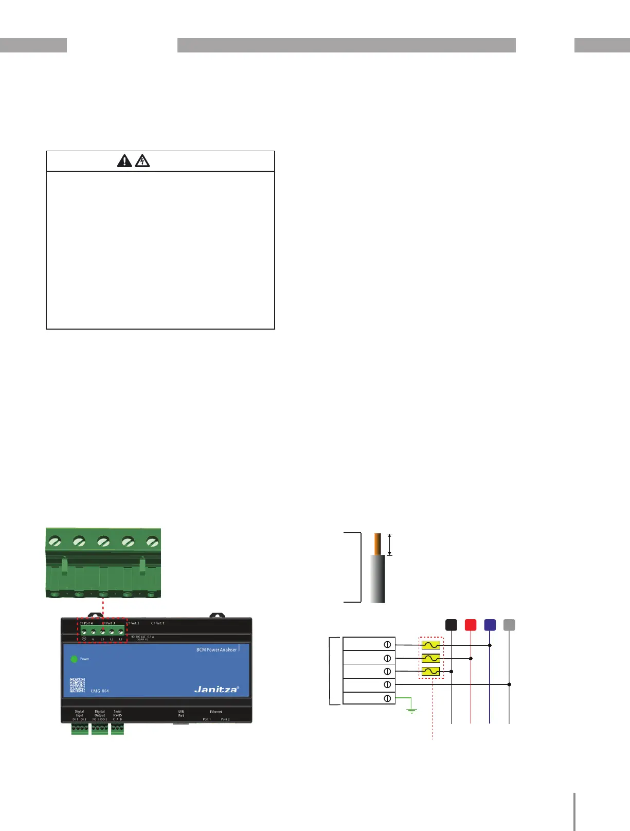
VOLTAGE INPUT CONNECTOR
SOLID WIRE: 24-12 AWG / 0.205-3.31 MM²
STRANDED WIRE: 24-12 AWG / 0.205-3.31 MM²
TORQUE: 5.0 Lb-In / 0.56 Nm
G/E N L3 L2 L1
Do not exceed 5.5 mm
bare wire length on voltage
connection points.
5.5 mm (0.22”) Max
N
N
G/E
Recomended Overcurrent Protection:
0.5 A @ 300 VAC
L2 L3
VOLTAGE INPUT
L1
L2
L3
L1
Fig.: UMG 804 voltage connection wiring
10.1 Voltage input 230 V AC
Recommended overcurrent protection: 1.0 A @ 300 V AC
for technical data refer to „5. Technical data“
on page 13

 Loading...