www.janitza.com UMG 804
45
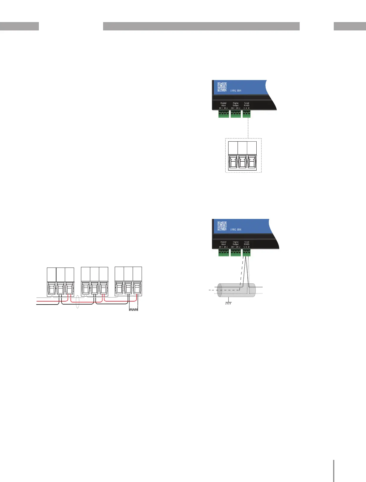
11. Serial Communications
The UMG 804 supports both Modbus TCP/IP and
Modbus RTU serials communications.
Connect the shielded 2 wire cable to the 2-wire
Modbus RS-485 network with the serial interface
jack.
Mechanically secure the RS-485 cable(s) where
they enter the electrical panel.
Connect serial cable(s) from the RS-485 loop to
the serial connector on the UMG 804. Connect
all RS-485 devices in a daisy-chain, and properly
terminate the chain as shown on fi gure.
Follow all applicable wiring and termination con-
nection guidelines for the standard in use.
Note that while both the Modbus RTU standards
identify requirements for RS-485 line polarization/
bias and termination, the value and placement
of these resistors varies for each standard. The
UMG 804 does not implement any RS-485 line
polarization/bias or termination internally. For the
RS-485 cable, use shielded, twisted-pair wire that
is voltage-rated for the installation.
Connect the shield to Earth Ground somewhere on
the RS-485 bus (single point connection only).
RS485 cable
(two wire + GND)
120 Ω termination
resistor when required
Data
GND
Tx-
Rx-
Tx+
Rx+
G (-) (+)
Data
GND
Tx-
Rx-
Tx+
Rx+
G (-) (+)
Data
GND
Tx-
Rx-
Tx+
Rx+
G (-) (+)
Fig.: Serial communications wiring
RS485 Bus
A
B
A
B
Data GND
Data
GND
Tx-
Rx-
Tx+
Rx+
G (-) (+)
SERIAL
RS-485
USB PORT
Data
GND
Tx-
Rx-
Tx+
Rx+
G (-) (+)
SERIAL
RS-485
Fig.: Serial communications port
Fig.: Serial communications port (detail)
 Loading...