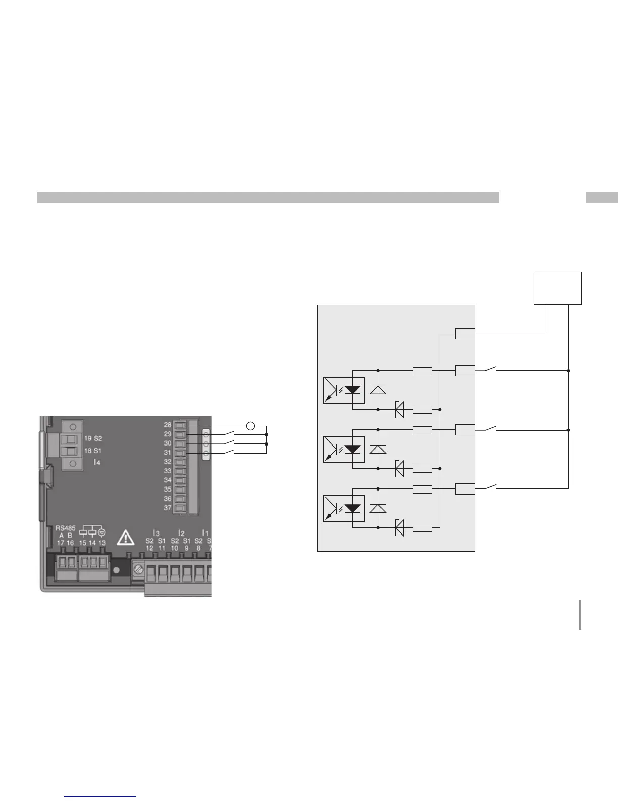
Digital inputs
When allocating Group 2 as inputs, the UMG96 RM-E
has three digital inputs to each of which you can
connect one signal transducer. When a signal is present,
the corresponding LED lights up green.
An input signal is detected on a digital input if a voltage
of at least 10V and maximum 28V is applied and
where a current of at least 1mA and maximum 6mA
flows at the same time. Wiring longer than 30m must
be screened.
Note the correct polarity of the supply voltage!
-
+
24V DC
S1
S2
External
Auxiliary voltage
28
29
30
31
2k21
2k21
2k21
2k21
2k21
2k21
2k21
Digital
Input 1
Digital
Input 2
Digital
Input 3
UMG 96RM-E
Digital inputs 1-3
Fig. Example for the connection of external switch
contacts S1 and S2 to digital inputs 1 and 2.
-
+
Fig. Connection
example for digital
inputs.
Group 2
S3