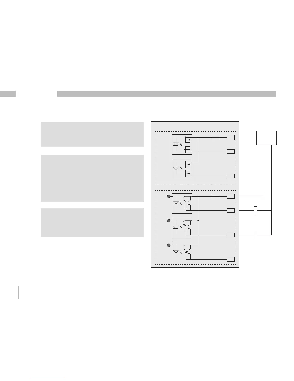
DC connection example
Fig. Example for two relays connected to
the digital outputs
K2
External
Auxiliary voltage
+
24V DC
-
K1
DC
DC
28
29
30
31
Digital Ouput 3
Digital Ouput 4
Digital Ouput 5
13
14
15
Digital Ouput 1
Digital Ouput 2
UMG 96RM-E
Group 1:
Group 2:
LEDLEDLED
C
When using the digital outputs as pulse
outputs the auxiliary voltage (DC) must
have a max. residual ripple of 5%.
C
Functions for the digital outputs can
be adjusted clearly in the GridVis
software (Download: www.janitza.com).
A connection between the UMG 96RM-E
and the PC via an interface is required for
the use of the GridVis software.
m
Caution!
Digital outputs are not short-circuit proof.