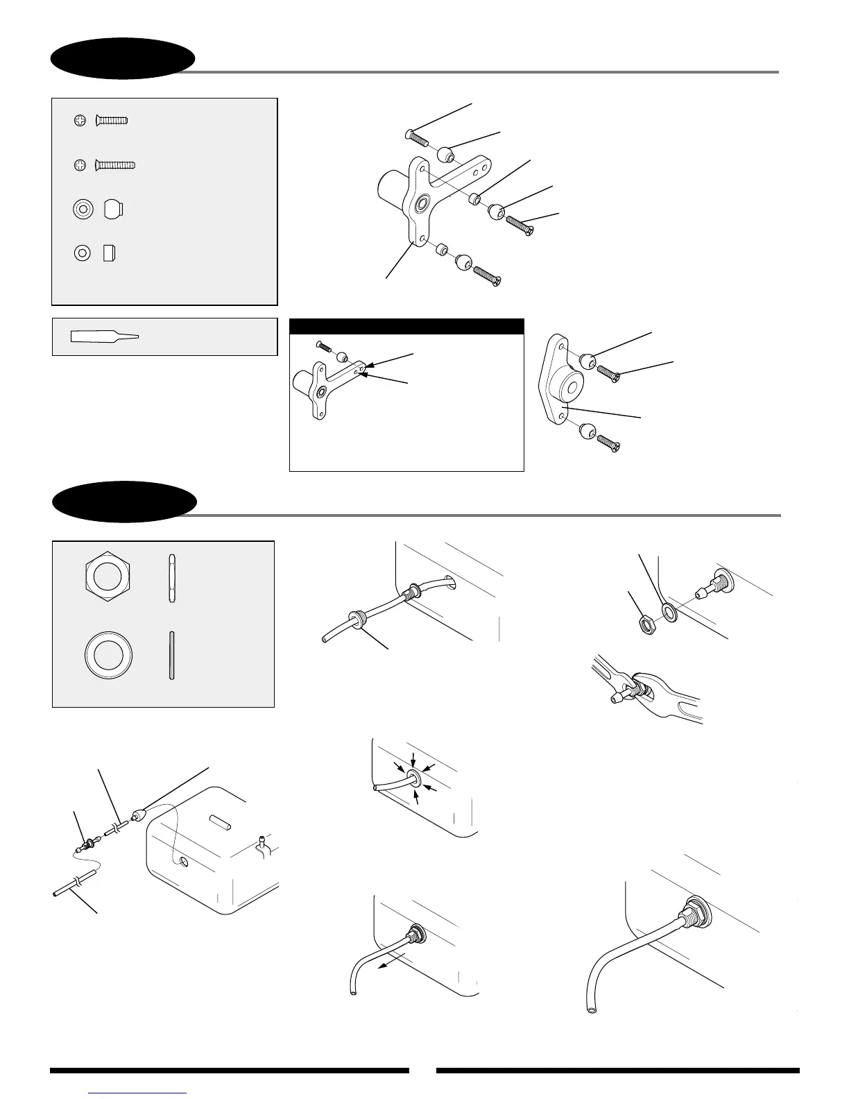
Use two wrenches if necessary
to secure tank nipple.
1-4
FUEL TANK ASSEMBLY (BAG #6)
1. Cut the small silicone fuel
tubing(included) to a length of 77 mm.
Next, connect the fuel tank clunk,
nipple, and medium silicone fuel
tubing (not included) as shown above.
Fuel
Tank
Clunk
Medium Silicone Fuel
Tubing (not included) —
Connect to engine carburetor.
Nipple
Silicone Tube (small)
Use tubing included in
seperate package in kit.
4. Pull the medium fuel tubing out of the
fuel tank until the threads of the fuel tank
nipple are exposed.
Nut, 7 mm
...........1 pc
Washer, 7 x 12 x 1 mm
...........1 pc
Complete Assembly
5. Remove the medium silicone fuel
tubing from the nipple and secure
the nipple to the fuel tank using
the 7 x 12 x 1 mm washer and
7 mm nut supplied. Be sure to
secure this assembly firmly to
avoid leakage.
Nut, 7 mm
Washer, 7 x 12 x 1 mm
2. Insert the assembly into the fuel tank
opening so that the nipple is inside the
tank. Next, slide the fuel tank grommet
over the medium fuel tubing
.
Fuel Tank Grommet
1-3
T-ARM LEVER ASSEMBLY
3. Inset the fuel tank grommet into the
fuel tank opening, making sure that it
is fully seated.
Use Red Threadlock
on all screws
.......................... 4 pc
.................... 4 pcs
.......................... 8 pcs
Flat Head Screw, 2 x 10 mm
Flat Head Screw, 2 x 8 mm
Steel Joint Ball
..............................4 pcs
Joint Ball Spacer, 2.2 mm
Flat Head Screw, 2 x 10 mm (4 pcs)
Flat Head Screw, 2 x 8 mm (2 pcs)
Steel Joint Ball
Steel Joint Ball (6 pcs)
Joint Ball Spacer, 2.2 mm (4 pcs)
T-Arm Assembly
Flat Head Screw,
2 x 8 mm (2 pcs)
Elevator Control Arm
Steel Joint Ball (2 pcs)
Wide Range
Standard Range
*
*Connect the control ball to the
T-Arms in the standard range
position as shown.
Note: