6-2
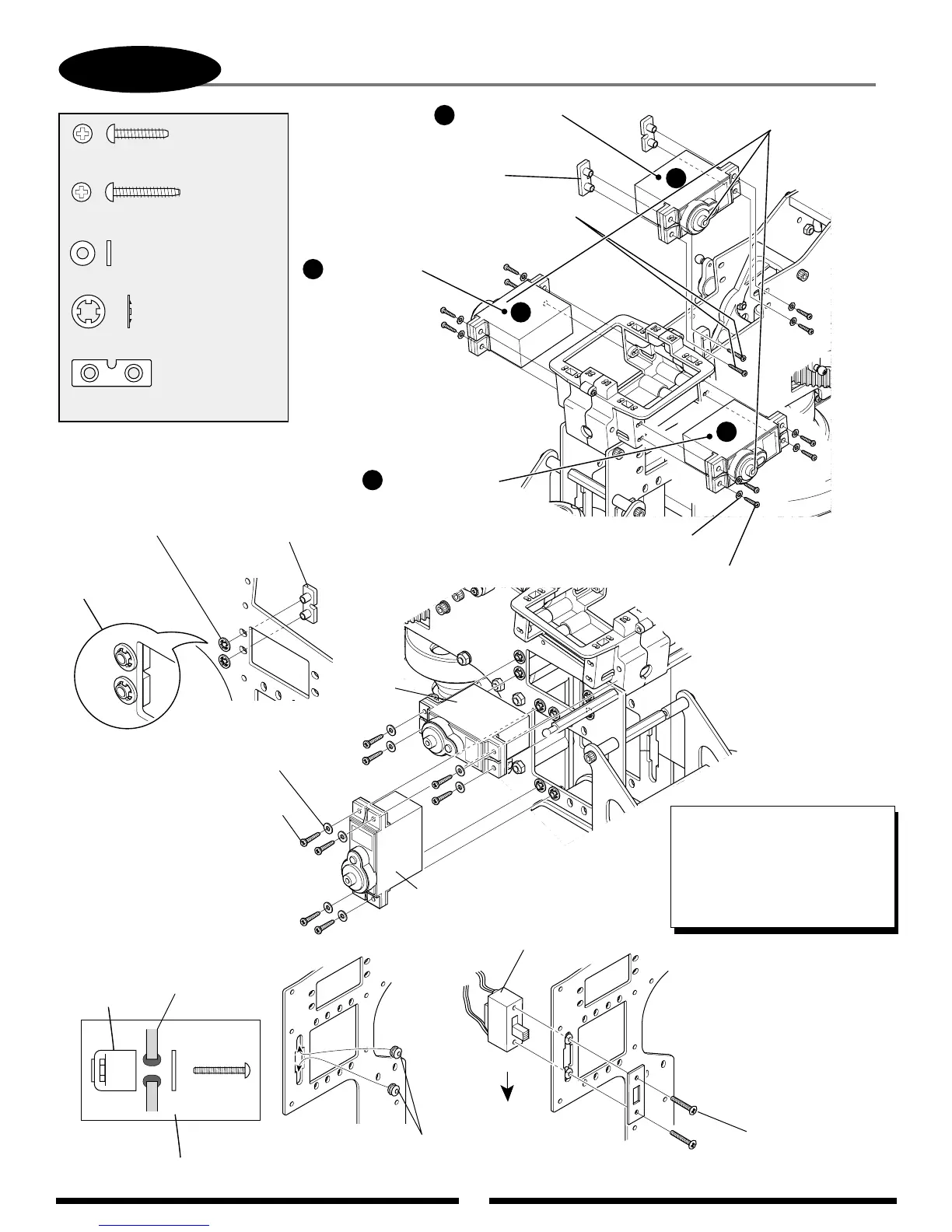
SERVO/SWITCH HARNESS INSTALLATION
................20 pcs
Self Tapping Screw, 2.6 x 12 mm
Self Tapping
Screw, 2.6 x 12 mm (8 pcs)
Switch Dampener
Rubber (2 pcs)
Switch Harness
Screws Supplied
with Switch
Flat Washer, 2.6 mm (8 pcs)
CA Stopper Ring, 3.5 mm
Type-B Servo
Mounting Plate
...............................20 pcs
...........................8 pcs
Flat Washer, 2.6 mm
CA Stopper Ring, 3.5 mm
Type-B Servo Mounting Plate
.......................4 pcs
* Note correct servo
output shaft orientation
during installation.
Attach as shown.
Switch
Switch Plate
Dampener Rubber
(2 pcs)
Off
On
TEAM TIP: When installing the
switch harness, position it so
that "Up" is off and "Down" is the
on position. This will prevent the
switch from accidentally being
turned off in a hard landing
or auto.
.............2 pcs
Self Tapping Screw, 2.6 x 15 mm
Type-B Servo
Mounting Plate (2 pcs)
Self Tapping Screw, 2.6 x 12 mm (10 pcs)
Self Tapping Screw, 2.6 x 15 mm (2 pcs)
*This portion only. (without washer)
Flat Washer, 2.6 mm (10 pcs)
Collective Servo
(Ch6)
Elevator Servo
(Ch3)
Aileron Servo
(Ch2)
Note output
shaft direction.
*
A
A
B
B
C
C
Rudder
Servo
Throttle
Servo