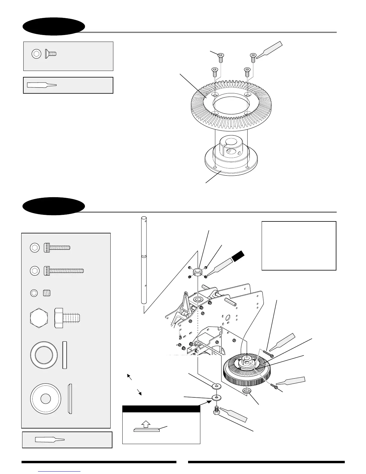
3-2
MAIN SHAFT/MAIN DRIVE GEAR INSTALLATION
Main Shaft Collar
Set Screw
4 x 4 mm (4 pcs)
Hex Head Bolt, 6 x 10 mm
Socket Head
Bolt, 3 x 20 mm
Bevel Gear
Assembly
Main Drive
Gear Assembly
Washer, 10 x 16 x 2.5 mm
(fits between bottom bearing
and auto-rotation unit)
Socket Head Bolt, 3 x 12 mm
3-1B
BEVEL GEAR ASSEMBLY
4 pcs
Red
Main Shaft Washer
Red
Special Washer, 10 x 6 x 0.5 mm
Red
Red
Use Red
Threadlock
........................4 pcs
......1 pc
...............1 pc
...........1 pc
Set Screw, 4 x 4 mm
Hex Head Bolt, 6 x 10 mm
Steel Washer, 10 x 16 x 2.5 mm
Main Shaft Washer
Main Shaft Washer Direction
Bevel Cutting
Up
Note:
Bevel Gear
Bevel Gear Hub
Flat Head Bolt, 3 x 6 mm
Flat Head Bolt, 3 x 6 mm (4 pcs)
...................... 4 pcs
Use Red Threadlock
Red
Attach the bevel gear hub as shown.
Be sure not to overtighten the four 3 mm bolts
as this could distort the bevel gear.
Socket Head Bolt, 3 x 12 mm
..... 1 pc
Socket Head Bolt, 3 x 20 mm
... 1 pc
Assembly Steps
1. Secure the bottom 6 x 10 mm
bolt to the shaft.
2. Pull up on the shaft and secure
the main shaft collar using the
4-4 mm set screws.
3. Secure the bevel gear assembly.
Both washers fit below
bottom bearing block.