90
90
90
90
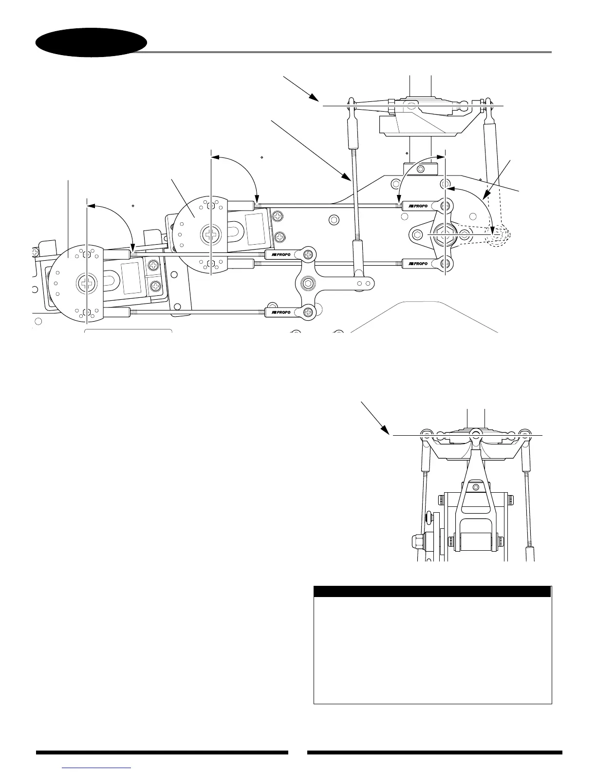
Check to insure the
swashplate is level on
the fore-aft axis.
7-7
CHECKING THE SWASHPLATE FOR LEVEL
Check to insure that the
swashplate is level on the left/right axis.
Reconfirm
that the
elevator
arm is at 90°.
Adjust the control rods as needed until the swashplate
is level with all servos in their neutral (90°) position.
Top Servo (A)
Left Servo (C)
After the control linkages have been attached to the
swashplate, it will be necessary to check the swashplate to
insure that it is level. To do this, turn on the radio system and
place the collective stick in the center position as before. Next,
check to make sure that all trim levers and knobs are also in
their center position.
Check to insure that the servo arms are parallel to the
servos as adjusted in the previous step. If the servos are not
parallel, please refer to the sub-trim section 7-2 and readjust
as necessary.
Once it’s determined that the servo arms are parallel to
the servos as required, it will now be necessary to check the
swashplate to insure that it is also level or neutral in this
position. It is suggested that the swashplate first be checked
from the rear of the model to insure that it’s level from left to
right. If the swashplate is not level as compared to the frame of
the model, adjust either the left or right servo control rods as
needed. To determine which rod needs adjustment, it may be
helpful to view the swashplate from the left and right side view
of the model to determine which side is high or low.
Once this left to right adjustment is completed, it will
now be necessary to check the fore/aft position of the swashplate
to insure that it is also level on this axis. If the swashplate is not
level in the fore/aft axis, it is suggested that the adjustment be
made to the front servo control linkage as needed by slightly
repositioning the elevator control arm on the elevator a-arm
assembly, or adjusting both front servo control rods.
If you are unsure as to which linkage needs adjustment
or are having difficulty obtaining the correct adjustment, please
check the length of each control rod to insure that it is adjusted
to the correct length as outlined in Step 5-3.
If care was taken in the linkage assembly in Steps 4-6 and
7-3, little or no adjustment should be required in this step.
Only minor adjustments should be made to the lengths of
the control linkages at this time. Any major adjustments
indicates either incorrect linkage lengths or incorrect
servo arm positioning. If the control linkage lengths are
altered from the recommended lengths more that one or
two turns, this will have a great effect on the range and
settings of the collective pitch in later steps.
Note: