Socket Head
Bolt, 3 x 40 mm (2 pcs)
6-1
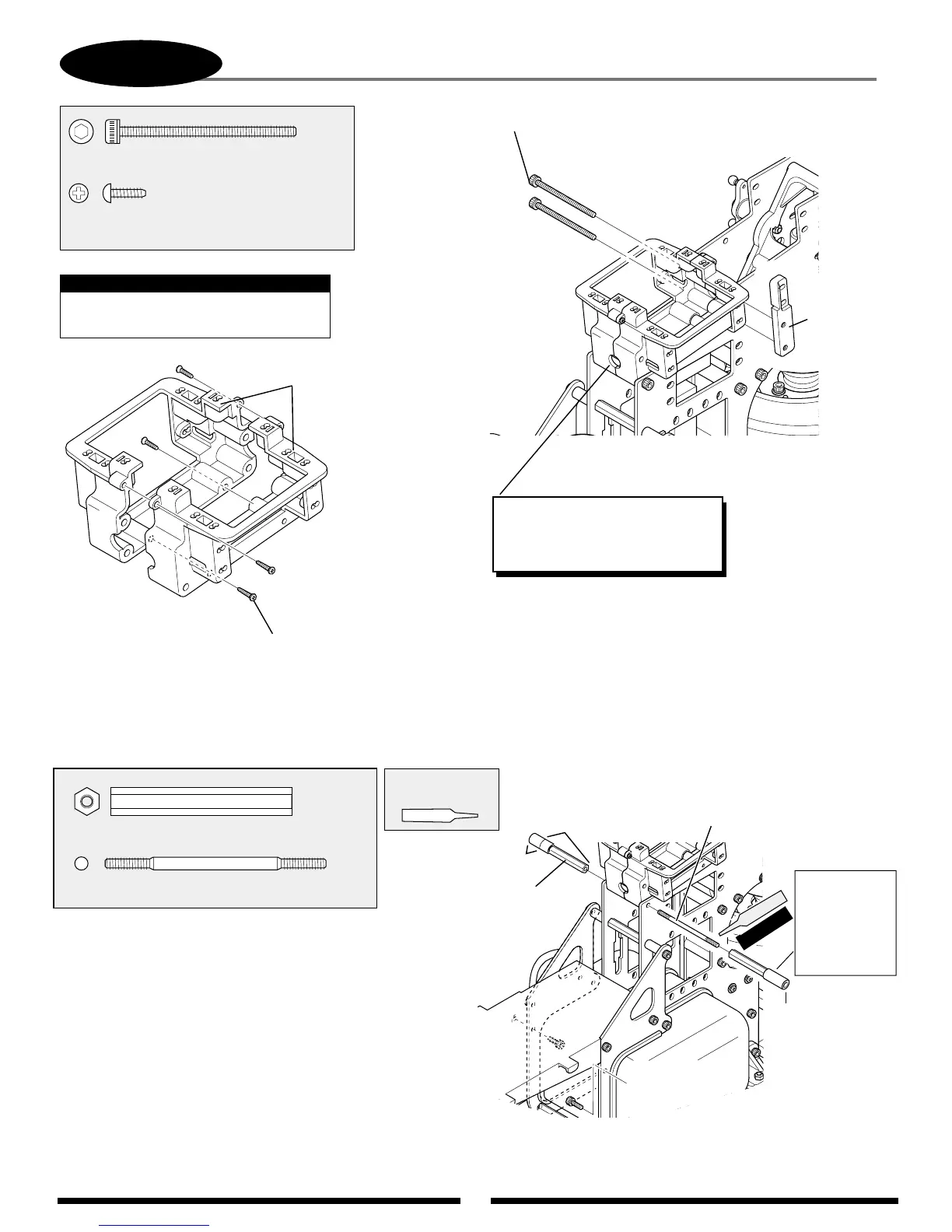
UPPER SERVO TRAY/BODY MOUNT ATTACHMENT
Socket Head Bolt, 3 x 40 mm
...3 pcs
Self Tapping Screw, 2.6 x 8 mm
..........................................4 pcs
When installing the servo tray, be
careful not to overtighten the screws.
Note:
Self Tapping
Screw, 2.6 x 8 mm (4 pcs)
Servo Tray
Both Si
des
Threaded Rod, 3 x 50 mm
Threaded Rod,
3 x 50 mm
..1 pc
Cross Member, 41 mm
........2 pcs
Cross Member
41 mm (2 pcs)
BODY MOUNT ATTACHMENT
Use Red
Threadlock
TEAM TIP: Increase the size of the
hole using a Dremel tool. This will
allow for easier insertion of the
servo leads.
Red
CCPM
Aluminum
Servo Mount
Standard
Fuel Tubing
(Not included;
use remaining
from engine/fuel
tank installation.)
8 mm
20 mm
Add two 20 mm
pieces of fuel tubing
to the standoffs as
shown so that they
protrude 8 mm
from the end of the
standoff. These will
support the canopy.