2-2
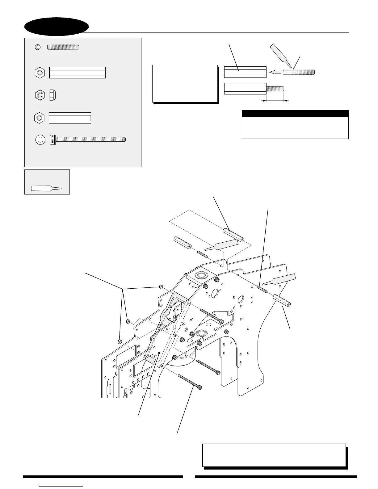
MAIN FRAME ASSEMBLY: CROSSMEMBER INSTALLATION
Socket Head Bolt, 3 x 40 mm (3 pcs)
Cross Member A
(note correct direction)
Nylon Lock
Nut, 3 mm (3 pcs)
Use Red
Threadlock
*TEAM TIP: Don’t tighten bolts completely at this time.
These bolts will be tightened in Step 3-8.
Set Screw,
3 x 18 mm (2 pcs)
Cross Member, 24 mm
10 mm
Red
*TEAM TIP: Do not apply
Threadlock to bolts unless
you will procede through
Step 3-8 during this
building session.
Cross Member,
24 mm (2 pcs)
Cross Member, 32 mm
Set Screw, 3 x 18 mm (2 pcs)
Red
Nylon Lock Nut, 3 mm
...................3 pcs
Socket Head Bolt, 3 x 40 mm....3 pcs
Cross Member, 24 mm
............2 pcs
Set Screw, 3 x 18 mm
.....................2 pcs
Cross Member, 32 mm
.....1 pc
Red
When installing the cross member A,
be careful not to over tighten.
Note: