3-3
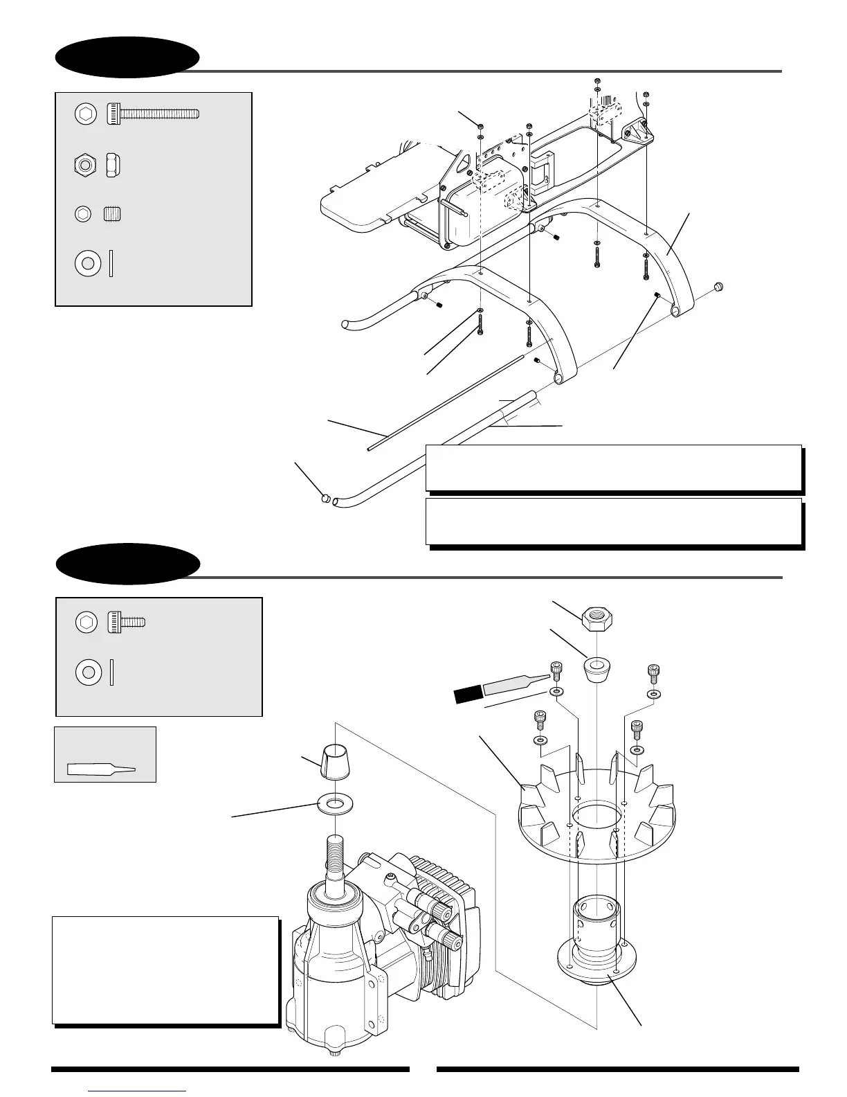
LANDING GEAR ASSEMBLY INSTALLATION
...4 pcs
..........................4 pcs
............................8 pcs
Socket Head Bolt, 3 x 20 mm
Socket Head Bolt, 3 x 20 mm (4 pcs)
Nylon Lock Nut, 3 mm
Nylon Lock Nut, 3 mm (4 pcs)
Flat Washer, 3 mm
Flat Washer, 3 mm (8 pcs)
.........................4 pcs
Set Screw, 4 x 4 mm
Set Screw, 4 x 4 mm (4 pcs)
Antenna Tube
Landing Skid (2 pcs)
Landing Struts (2 pcs)
Landing Skid Cap
Use CA adhesive
to attach.
TEAM TIP: The four 3 x 20 mm landing gear bolts can be installed
from the top (opposite diagram) for a cleaner appearance.
TEAM TIP: The landing skid tubes can be shortened by 3" to save
weight and provide a cleaner apearance. — Len
TEAM TIP: The landing skid tubes can be shortened by 3"
to save weight.
3-4
COOLING FAN/HUB INSTALLATION
Socket Head Bolt, 3 x 6 mm
Socket Head Bolt, 3 x 6 mm (4 pcs)
..................4 pcs
4 pcs
Nut (supplied with engine)
Washer
(supplied with engine)
Use for O.S. engines
only. Omit for YS
engines.
Taper Collet Upper (small)
Taper Collet Lower
(large)
...........................4 pcs
Flat Washer, 3 mm
Flat Washer, 3 mm (4 pcs)
Cooling Fan
Blades
Cooling Fan Hub
Use Red
Threadlock
*
*
*
*
*
Tighten bolts evenly
to prevent warping.
TEAM TIP: It is recommended that a
piston locking tool be used to properly
secure the fan assembly to the engine.
When using a piston locking tool, it is
necessary to also hold the fan assembly
to prevent excess loads from being
applied to the piston.
3"
Shorten
(optional)
Red