2-4
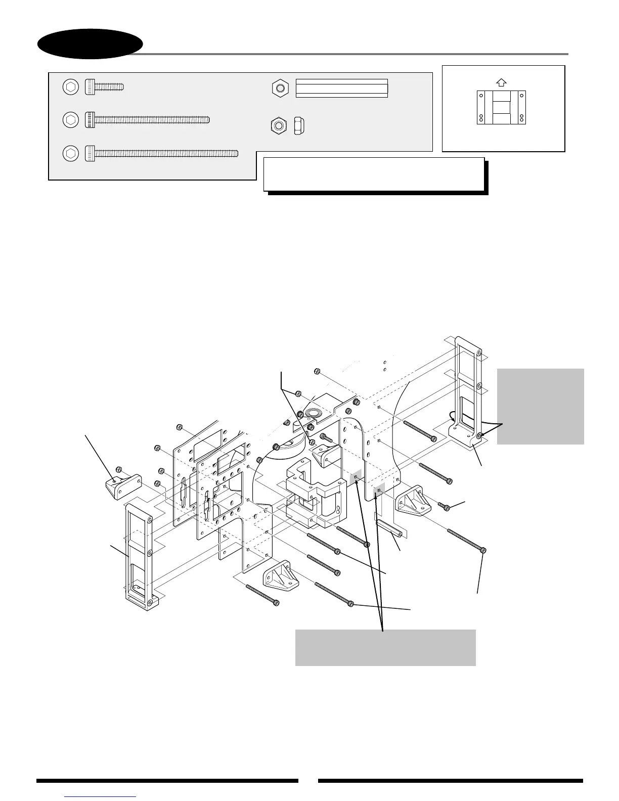
MAIN FRAME ASSEMBLY: ENGINE MOUNT/CROSS MEMBER INSTALLATION
Socket Head Bolt, 3 x 50 mm (2 pcs)
Cross Member B
(note correct direction)
Cross Member, 32 mm
Cross Member B
(note direction)
Landing Struts
Adaptor (4 pcs)
Socket Head
Bolt, 3 x 40 mm
(6 pcs)
Socket Head
Bolt, 3 x 10 mm (2 pcs)
(Do not use threadlock.)
Nylon Lock
Nut, 3 mm
(8 pcs)
*
*
*
*
*
*
*
*
*
A) Remove the two raised portions from cross member “B” as shown.
B) Remove a 1/2" x 3/4" portion of the clear coating from the inside of each
main frame as shown.
Remove these two
raised portions
using a knife or
file so that they
are flush with
the cross member
side.
Remove a 1/2" x 3/4" portion of the clear
coating from the inside of each frame
plate as shown.
1/2"
3/4"
.....2 pcs
....6 pcs
................................2 pcs
.....................................8 pcs
Socket Head Bolt, 3 x 10 mm
Socket Head Bolt, 3 x 40 mm
Socket Head Bolt, 3 x 50 mm
Nylon Lock Nut, 3 mm
Cross Member, 32 mm
.....1 pc
Up
O.S. Engines and YS Engines
Engine Mount Direction
*TEAM TIP: Do not tighten bolts completly as this
time. These bolts will be tightened in Step 3-8.