69
PREASSEMBLED COMPONENTS
P-1
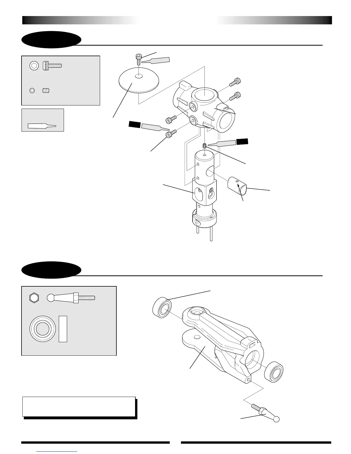
ASSEMBLY PROCESS – MAIN ROTOR HEAD 1
P-2
ASSEMBLY PROCESS – MAIN ROTOR HEAD 2
Control Ball, 14 mm
Control Ball, 14mm (2 pcs)
...2 pcs
Bearing, 8 x 16 x 5 mm
Bearing, 8 x 16 x 5 mm (4 pcs)
Main Blade Holder
......................4 pcs
4 pcs
Use caution when inserting the
main blade holder bearings so
as not to distort/damage the
main blade holders.
Make two main blade holders.
Socket Head Bolt, 3 x 8 mm
Socket Head Bolt, 3 x 8 mm
Socket Head Bolt, 3 x 8 mm (4 pcs)
Head Button
Main Rotor Head Body
Set Screw, 3 x 4 mm
Spindle Shaft Guide
Main Rotor Hub Assembly
................5 pcs
.........................1 pc
Set Screw, 3 x 4 mm
Position hole at top to
engage set screw.
ALL
TEAM TIP: JB Weld the bearings into the blade
holders to reduce play in the blade holders.
Use Red
Threadlock
Red
Red
Red