GPS Navigator J-NAV500
20
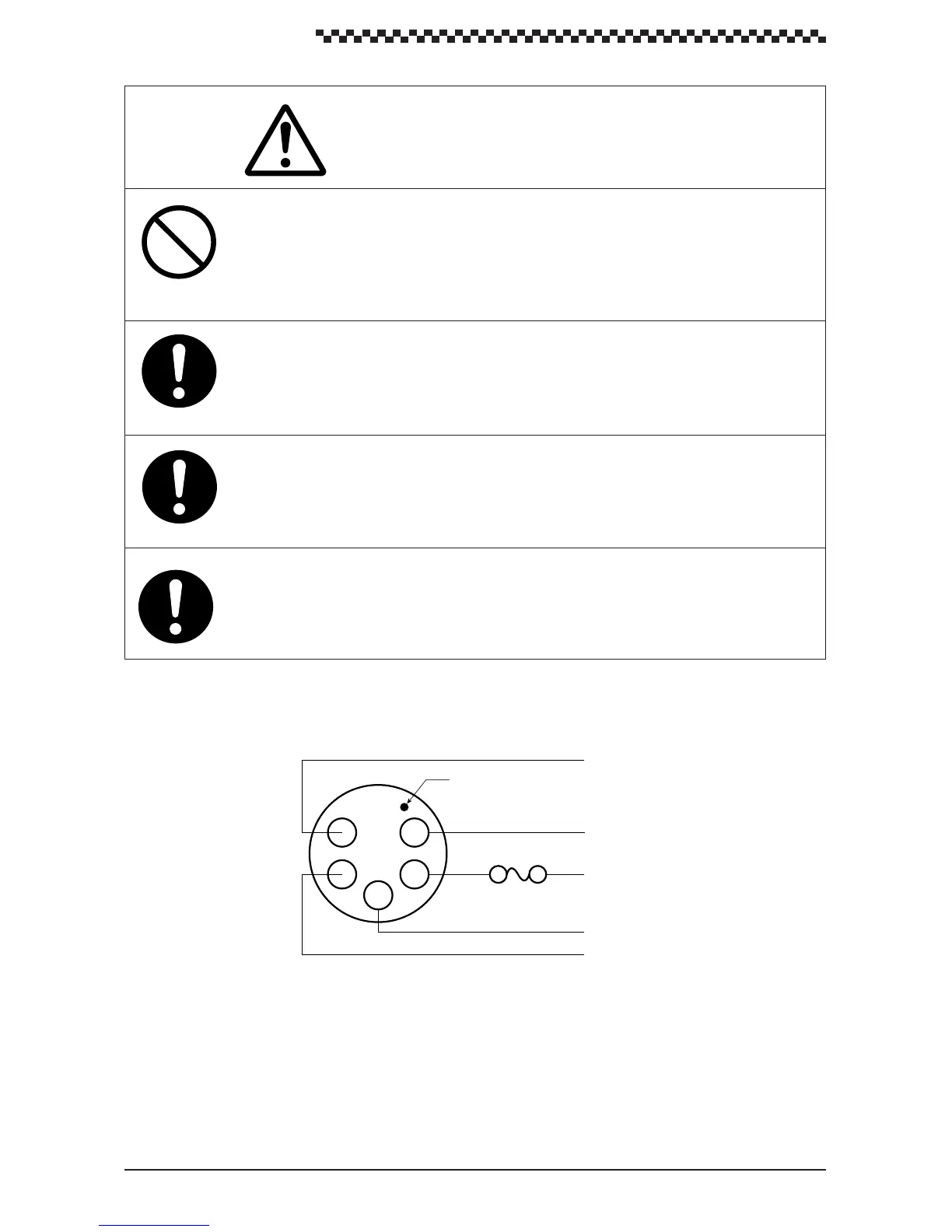
Figure 3-5 is a power cable wiring diagram. The power cable include the following wires: +12 VDC,
-12 VDC, DATA COM, DATA OUT+ and DATA IN+. Each wire is labeled.
Figure 3-5
Connect the red cable to the plus terminal and the black cable to the negative terminal
of the 12 VDC power supply. Note that reversing the cables could lead to equipment
damage.
Use only a fuse with the designated rating. Use of other fuses could lead to fire or
breakdown.
Model ; MF60NR-2A
Do not connect this unit and the GPS/DGPS receiver to ground when used with a
“floating” battery. Should they be connected to ground, large current will flow from this
unit or the GPS/DGPS receiver to ground and could cause fire or equipment break-
down.
When the data signal cables are not to be used, insulate the cable ends using
insulation tape to prevent cable short-circuit. Otherwise, the equipment may be
damaged.
CAUTION
The unit is intended for use on vessels with 12 VDC power systems and can operate as long as the DC
supply is maintained between 10.8 and 16 volts. The DC power system can be negative ground or can
be used without a ground connection in a ÔfloatingÓ power supply.
5
Make indicating pin 1 location
White
DATA IN+
DATA OUT+
+12 VDC
–12VDC
DATA COM
Red
Black
Green
Yellow
Fuse 2A
1
2
3
4
 Loading...