EasyManua.ls Logo

JRC J-NAV 500 User Manual

JRC J-NAV 500
85 pages
To Next Page IconTo Next Page
Page #1 background imageLoading...
Page #1 background image
INSTRUCTION MANUAL
GPS NAVIGATOR
NWZ-4551
For further information contact :
HEAD OFFICE &
SALES DEPT.
Akasaka Twin Tower(MAIN),
17-22, Akasaka 2-chome, Minato-ku,
Tokyo 107-8432 JAPAN
Phone
Fax
Telex
CODE No.7ZPNA0115
MODEL DC-50-NWZ-4551
Made in JAPAN
Mar. 1998 (First Edition)
May. 1998 KP (2500)
: +81-3-3584-8711
: +81-3-3584-8715
: 0242-5420 JRCTOK J
MAIN PLANT
1-1, Shimorenjaku 5-chome, Mitaka-shi,
Tokyo 181-8510 JAPAN
Phone
Fax
Telex
: +81-422-45-9111
: +81-422-45-9110
02822-351 JRCMTK J
MODE
MENU
MOB
DIM
CONT
CLR
PWR
EVENT
GOTO
OFF
OFF
PUSH
GPS NAVIGATOR

Table of Contents

Question and Answer IconNeed help?

Do you have a question about the JRC J-NAV 500 and is the answer not in the manual?

JRC J-NAV 500 Specifications

General IconGeneral
BrandJRC
ModelJ-NAV 500
CategoryGPS
LanguageEnglish

Summary

Before you begin

Related symbols

Explains the meaning of warning and caution symbols used in the manual.

Symbol examples

Illustrates common symbols for danger, prohibition, and instruction.

Safety Precautions

General WARNING Precautions

Details critical safety warnings to prevent severe injury or property damage.

CAUTION Precautions

General CAUTION Precautions

Outlines important cautions to prevent minor injury or property damage.

1. Overview

1.5 Equipment connections

3. Installation

3.1 Display installation

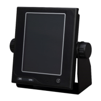
Details the process for installing the display unit.

Choosing the location

Provides criteria for selecting an optimal mounting location for the unit.

Mounting the unit

Describes the steps for physically mounting the display unit using a bracket.

3.2 Cable connections

GPS/DGPS receiver connection

Explains how to connect the GPS/DGPS receiver to the unit.

Power cable connection

Details the procedure for connecting the power cable and associated warnings.

3.3 EMC Installation & Service Guidelines

Servicing and Safety

Covers safety during servicing and emphasizes professional repair services.

4. Operation

4.2 Turning the unit on/off

4.4 Switching between Main Display Modes

4.5 Main Display Modes

4.5.1 POSITION display mode

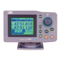
Displays current position and navigation information like bearing and distance.

4.5.2 NAVIGATION display mode

Shows bearing, distance, course deviation, and arrival time information.

4.5.3 CDI display mode

Provides a graphic representation of course deviation and steering direction.

4.5.4 PLOT display mode and setting the plot scale

Displays track and route lines graphically and allows plot scale adjustment.

4.6 Basic menu selection operations

4.8 Setting Alarms (Arrival/Anchor/Off-course/DGPS)

Arrival alarm

Configures an alarm to alert when the vessel is within a specified distance of a waypoint.

Anchor alarm

Sets an alarm to monitor the vessel's position while anchored.

Off-course alarm

Configures an alarm for when the vessel deviates from its set course.

4.9 Navigation using direct route [GOTO]

4.10 Navigation according to route plans

4.11 Entering current position as a waypoint [EVENT]

4.12 Man-Overboard Mode

4.13 Position Display Mode/Position Correction/Geodetic System Correction/Magnetic Compass Correction

4.14 Setting Navigation Display Modes and Units

4.15 Setting CDI range and Display Time Format

4.16 Setting Plotting Information

4.17 Entering Waypoints

4.17.1 Editing Waypoint Lists

Details how to view and edit existing waypoint entries.

4.17.2 Storing waypoints

Guides on entering new waypoints via latitude/longitude, TDs, or bearing/distance.

4.17.3 Erasing, copying and measuring waypoints

4.18 Setting Route Plans

4.18.1 Making route plan

Describes the procedure for creating new route plans by linking waypoints.

4.18.2 Editing route plan

Explains how to insert or delete waypoints within existing route plans.

4.19 Setting GPS information

4.19.1 Setting position fix mode and averaging for GPS

Configures position fixing mode (2D/Auto) and sets averaging time for GPS data.

4.19.2 Initializing GPS/DGPS receiver

Explains how to initialize the GPS/DGPS receiver to reduce initial position fixing time.

4.20 Setting Data Output and transmit memory data

4.22 Performing Master Reset

5. Maintenance and Inspection

General Safety Precautions

Outlines essential safety measures and warnings for maintenance and inspection.

Related product manuals