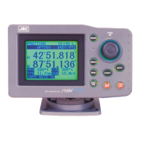
GPS Navigator J-NAV500
21
However, the unit cannot be used on positive ground vessels.
Power lead connections
1. Connect the black -12 VDC power cable to the negative pole of the vessel battery.
2. Connect the red +12 VDC power cable to the positive pole of the vessel battery.
3. Firmly connect the power cables in the DC PWR/DATA connector on the rear panel of the unit.
• On a large ship, connect the power cable leads to the DC distribution board. Since a 2 A fuse is
used in the unit, connect it to a circuit breaker with 3 A or greater capacity.
• On a small ship, connect the power cables directly to the main battery insulation switch or breaker.
• Connect the unit to it’s own circuit breaker. Do not connect it to a circuit breaker also used for radar
and other equipment.
• To avoid electromagnetic interference, route the wiring of the unit as much as possible away from
other equipment.
• The power consumption of the unit is 6 watts when a GPS/DGPS receiver is connected; since line
loss becomes a problem at lengths of 3 meters or more, thicker cable has to be used. Use #12
AWG for cable length between 6 to 12 meters.
Data signal cable connections
The DATA OUT+, DATA IN+ and DATA COM signal cables can be used to connect to external
equipment using serial data connections. NMEA0183 sentences are output at all time.
Data signal cable connections
• Connect the DATA OUT+ (yellow), DATA IN+ (white) and DATA COM (green) cables to the
serial port of external equipment.
3.2.3 Ground connection
To connect to a beacon receiver with a whip antenna, a ground connection is required to improve
receiving performance. If the ship’s battery is a connected to negative ground, you can ground the
equipment using the hull of the vessel. If the ship’s battery is not connected to ground, use an insulating
DC-DC converter between the battery and the navigator before making a ground connection.
(Use an NBG-121 insulating converter for a 24 VDC battery.)
• Connect the E terminal on the back of the unit to the nearest vessel ground. Use #10 AWG or
thicker cable.
 Loading...