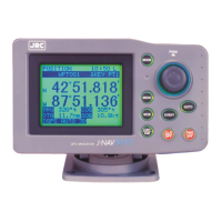
GPS Navigator J-NAV500
35
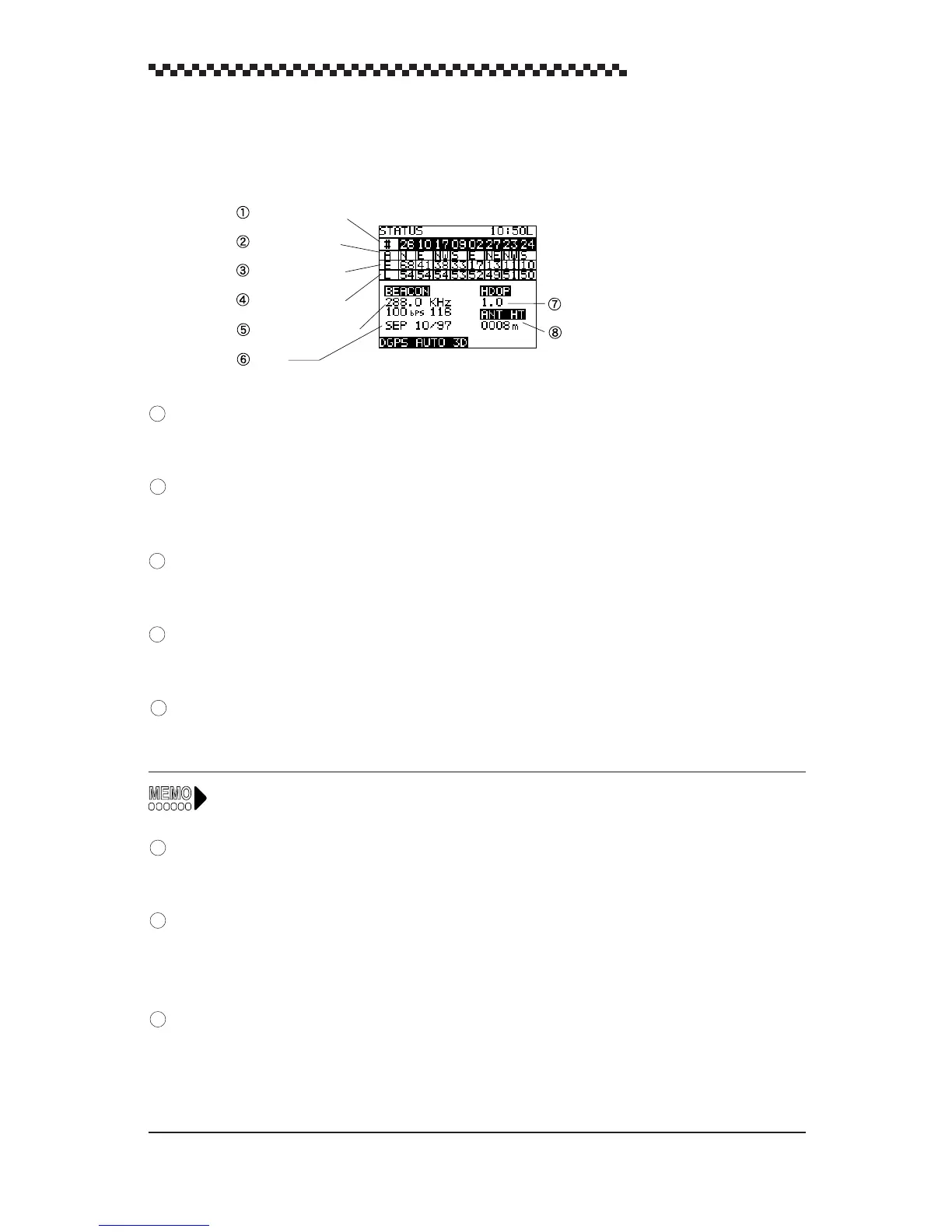
4.5.7 STATUS display mode
The [STATUS] display mode shows all relevant satellite data.
Satellite number
Displays numbers for the receiving satellites (8 of 01 to 32)
Azimuth angle
Displays the azimuth angle: N, NE, E, SE, S, SW, W, NW
Elevation angle
Displays the elevation angle to each satellite.
Receiving level
Displays the receiving level of each satellite. The greater the number, the higher is the level.
Beacon status
Displays the frequency, Baud rate and RSSI of DGPS beacon receiving signal.
RSSI: Receiving Signal Strength Indication
Date
Displays date derived from position fix. (month/day/year)
HDOP value
Indicates HDOP value. Position becomes more accurate as the HDOP value decreases. When the
HDOP value exceeds 4, the HDOP indicator flashes to notify that the positioning accuracy is poor.
Antenna height
In 3D mode, the height of the GPS/DGPS receiver obtained from position fixing is displayed.
Initial value are displayed when initialization is performed in 2D mode. (For details, see Section 4.19.2,
“Initializing GPS/DGPS receiver”). Initial values or the height obtained in previous 3D measurements
are displayed in an automatic mode.
Satellite number
Azimuth angle
Elevation angle
Receiving level
Beacon status
Date
HDOP value
Antenna height
1
2
3
4
5
6
7
8
 Loading...