4-44
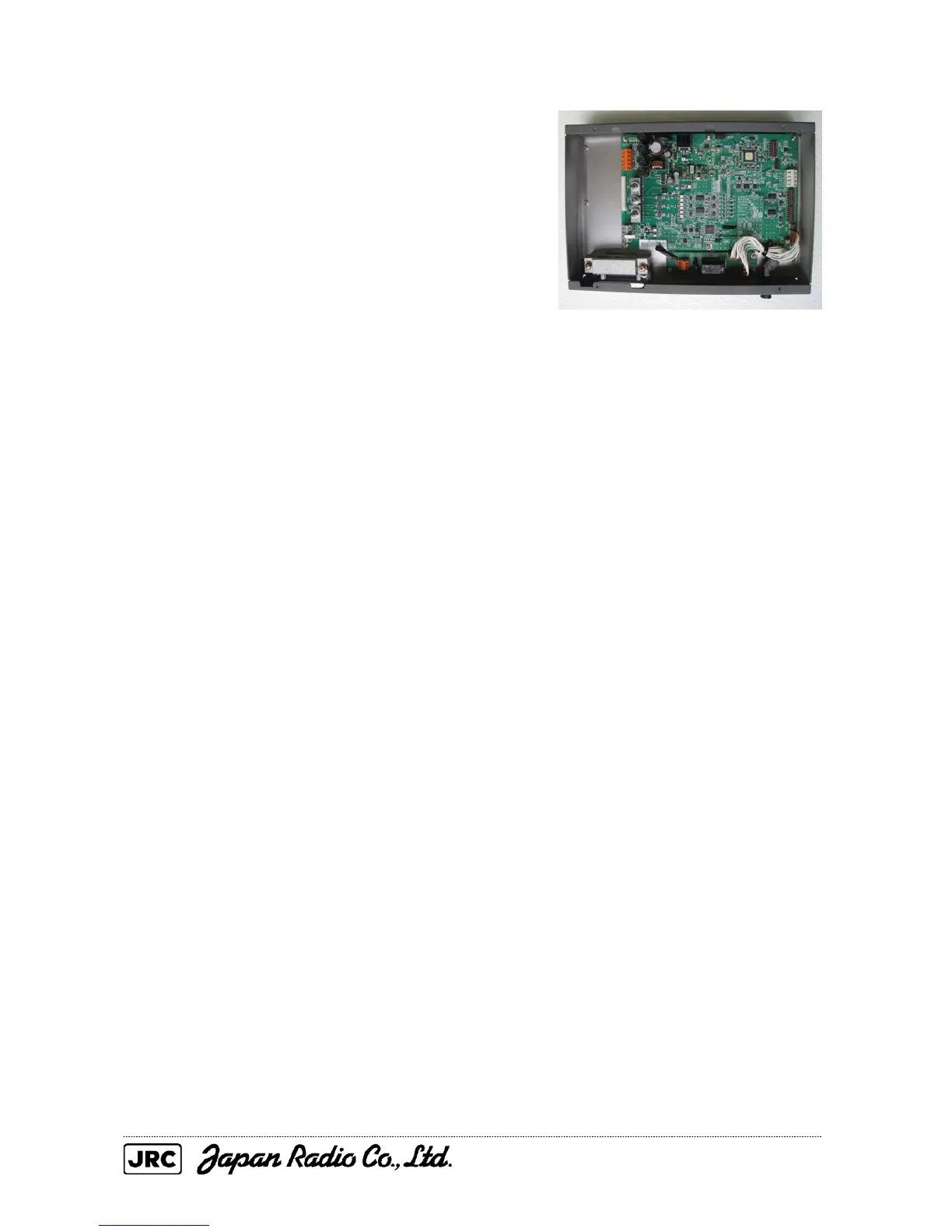
(4) Remove the six screws that secure the GYRO/LOG I/F
circuit, and replace it.
(Phillips screwdriver for 3 mm screws)
[Mounting]
(1) Check that the DIP switch settings of the GYRO I/F circuit are correct.
Check the GYRO I/F circuit fuses.
(2) Assemble the unit in reverse order of removal.
(3) Start the equipment, and set the true bearing value.
[Operation check]
(1) Check that an error message is not displayed.
(2) The true bearing value is traced correctly. (Resolution, and rotation direction)

 Loading...


