4-11
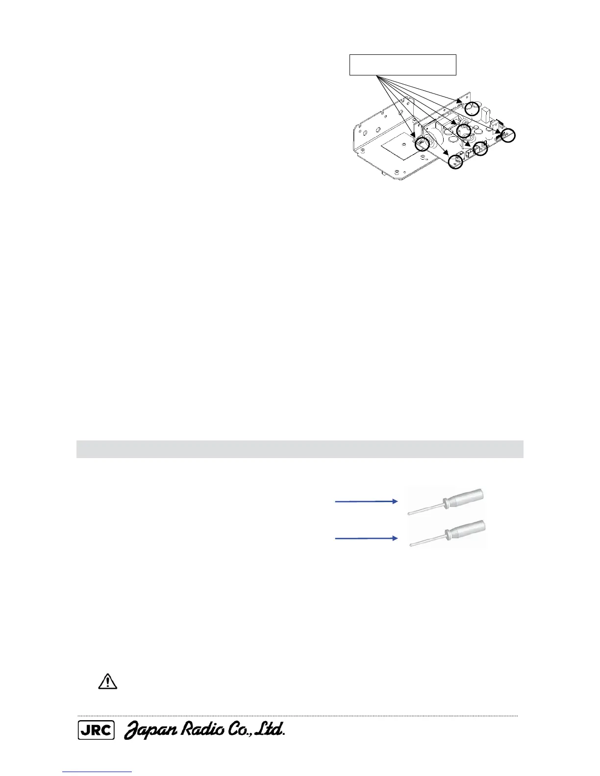
(3) Remove the screws (six M4 screws) holding
the power supply circuit board in place and
replace the power supply circuit board.
If the square heat radiation sheet on the
casing on the back of the power supply
circuit board (the soldered side) is damaged,
affix a new sheet to the replacement power
supply circuit board.
(4) After having replaced the power supply circuit board, reassemble the unit following
the disassembly procedure in the reverse order.
Do not forget to tighten the bolts and screws, and do not forget to reconnect the
cables.
[Operation check]
After having completed the replacement, follow the procedure below to check the
operation.
(1) Turn on the radar and emit radar waves once the countdown is finished, and
check that the radar image is correctly displayed.
4.1.8. T/R control circuit (CMC-1205R) replacement / NKE-2254
[Required tools]
• A Phillips screwdriver for 4 mm screws
• A Phillips screwdriver for 5 mm screws
• Tools for removing the scanner unit covers (See Section 4.1.2)
[Replacement procedure]
(1) Before beginning the replacement procedure, open the service engineer menu of
the radar display unit and back up the scanner unit data (transmission time and
motor rotation time).
If you do not back up this data, it will not be possible to maintain continuity in
scanner data such as the magnetron usage time.
Remove the six screws.

 Loading...


