4-8
[Operation check]
After completing the replacement work, check the operation by following the
procedure below.
(1)Turn on the radar, transmit radar signals when the countdown is finished, and
check that radar images are displayed normally. There shall be no abnormal noise
emitted when the motor starts running, when it is running, or when it stops.
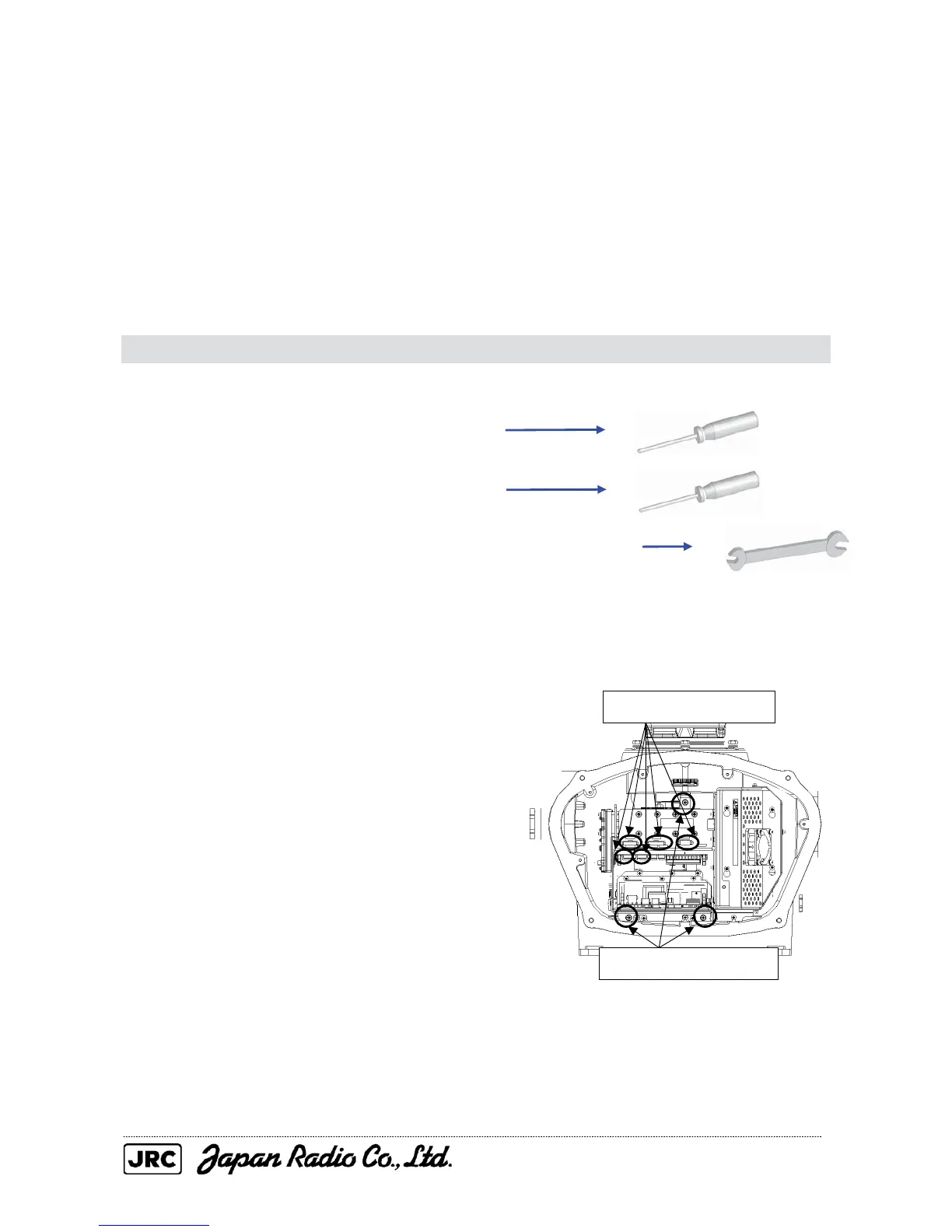
4.1.6. Modulator circuit (CPA-264) replacement / NKE-2254
[Required tools]
• A Phillips screwdriver for 4 mm screws
• A Phillips screwdriver for 5 mm screws
• Single-ended wrench (width across flats 7 mm for M4 bolts)
• Tools for removing the scanner unit covers (See Section 4.1.2.)
[Replacement procedure]
(1) Remove the cover on the right (starboard)
side (see Section 4.1.2), remove the cables
connected to the transmitter-receiver unit
and the screws (three M5 screws) holding
the transmitter-receiver unit in place, and
remove the transmitter-receiver unit.
Remove the five cables.
Remove the three screws.

 Loading...


