4-25
[Operation check]
After completing the replacement work, check the operation by following the
procedure below.
(1) Turn on the radar, transmit radar signals when the countdown is finished, and
check that radar images are displayed normally. There shall be no abnormal noise
emitted when the motor starts running, when it is running, or when it stops.
4.1.16. Motor Control Power Circuit Replacement for the NKE-2103
[Required tools]
• A Phillips screwdriver for 4 mm screws
• A Phillips screwdriver for 5 mm screws
• Tools for removing the scanner unit covers (See Section 4.1.2.)
[Replacement procedure]
(1) Open the top cover (see Section 4.1.2),
and remove the transmitter-receiver unit
(see Section 4.1.6).
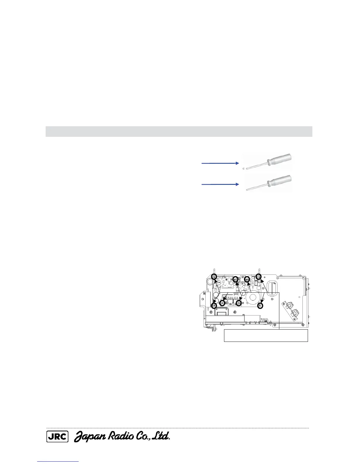
(2) Disconnect the cables from the motor
control power circuit, remove the eight
screws (M4) that secure the motor control
power circuit, and replace it.
(3) After the replacement of motor control power circuit, carry out the work in reverse
order of removal.
Be sure to tighten all the bolts and screws and connect all the cables.
Remove the eight screws (M4).

 Loading...


